ANTI-LOCK BRAKES
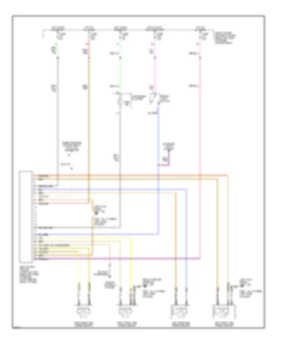
Anti-lock Brake Wiring Diagrams, with Traction Control for BMW 318ti 1997

List of elements for Anti-lock Brake Wiring Diagrams, with Traction Control for BMW 318ti 1997:
- (below center console) g302
- (left kick panel) g200
- (others)
- (z3)
- * 318ti, z3
- ** 318i, 318ic, 318is
- Abs hydraulic unit
- Abs hydraulic unit (rear left side of engine compartment back of left shock tower)
- Abs ind
- Abs pump motor relay
- Abs pump motor relay (power distributon box) (rear left side of engine compartment)
- Abs signal
- Abs signal instr cluster
- Asc lamp
- Asc switch
- Brake light switch
- Brake light switch (left footwell)
- Can high
- Can low
- Data link connector (rear of engine compartment)
- Engine control system
- Front power distribution box (rear left side of engine compartment)
- Fuse f10 30a
- Fuse f21 15a
- Fuse f27 5a
- Fuse f38 30a
- Fuse f46 15a
- G108
- G202 (left side of dash)
- G203 (right side of glove box)
- Ground
- Hot at all times
- Hot in accy, run and start
- Hot in run and start
- Instrument cluster
- Interior lights system
- Left front abs speed sensor
- Left front inlet valve
- Left front outlet valve
- Left front solenoid valve
- Left rear abs speed sensor
- Left rear inlet valve
- Left rear outlet valve
- Left rear solenoid valve
- Lf spd sens gnd
- Lf speed sensor abs
- Lr spd sens gnd
- Lr speed sensor abs
- Nca
- Rf spd sens gnd
- Rf speed sensor abs
- Right front abs speed sensor
- Right front inlet valve
- Right front outlet valve
- Right front solenoid valve
- Right rear abs speed sensor
- Right rear inlet valve
- Right rear outlet valve
- Right rear solenoid valve
- Rr spd sens gnd
- Rr speed sensor abs
- Rr speed signal dme
- Separating valve
- Seperator valve
- Slip control module (abs) (behind glove box)
- Txd diag
- Warning ind
Anti-lock Brake Wiring Diagrams, without Traction Control for BMW 318ti 1997
List of elements for Anti-lock Brake Wiring Diagrams, without Traction Control for BMW 318ti 1997:
- (all others)
- (below center console) g302
- (left kick panel) g200
- (raer of engine compartment) data link connector
- (z3)
- Abs control module/ hydraulic unit (rear left side of engine compt behind shock tower)
- Abs ind
- Brake light switch
- Engine controls system
- Exterior lights system
- Front power distribution box (rear left side of engine compartment)
- Fuse f10 30a
- Fuse f21 5a
- Fuse f27 5a
- Fuse f38 30a
- Fuse f46 15a
- G202 (left side of dash)
- Hot at all times
- Hot in accy, run and start
- Hot in run and start
- Instrument cluster
- Left front abs speed sensor
- Left rear abs speed sensor
- Nca
- Right front abs speed sensor
- Right rear abs speed sensor