ANTI-LOCK BRAKES
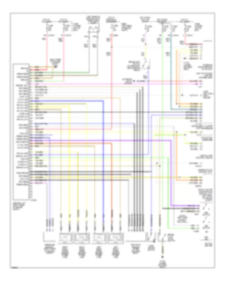
Anti-lock Brakes Wiring Diagram for BMW 325xi 2004
List of elements for Anti-lock Brakes Wiring Diagram for BMW 325xi 2004:
- (left footwell) obd ii socket
- (left rear of engine compt) precharge pump
- (right rear of engine compt) x170
- Abs/dsc unit (right rear of engine compt)
- Asc passive
- Brake fluid
- Brake fluid level
- Brake light
- Brakelight switch (on bracket, above brake pedal)
- Can high
- Can low
- Diag txd
- Digital motor electronics control unit (left rear of engine compt)
- Dsc switch
- E-box (left rear of engine compt)
- Exterior lights system
- Fuse f3 20a
- Fuse f33 5a
- Fuse f34 5a
- Fuse f35 50a
- Fuse f40 5a
- Fuse f53 30a
- Fuse f9 5a
- Fuse holder (glove box)
- Ground
- Hdc ind
- Hdc mode
- Hdc switch
- Hot at all times
- Hot in run or start
- Hot in run, accy or start
- Hot w/ dme relay energized
- Instrument cluster control module
- Left front speed sensor (wheel hub)
- Left rear speed sensor (wheel hub)
- Lf spd out
- Lf whl spd
- Light switching center control unit
- Lr spd out
- Lr whl spd
- Mirror fold-in control unit
- Navigation computer
- Nca
- Park brake
- Park brake switch
- Precharge
- Press sens
- Pressure sensor 1 (right rear of engine compt)
- Red
- Rf spd out
- Rf whl spd
- Right front speed sensor (wheel hub)
- Right rear speed sensor (wheel hub)
- Rpm rate sensor (under driver's seat)
- Rpm sens
- Rr whl out
- Rr whl spd
- Steering angle sensor (in column)
- Switch
- Switch center
- Tire failure control module
- Warn ind
- X10012 (left side of right footwell)
- X10015
- X10016
- X10313
- X1108 (under driver's seat)
- X11175
- X12
- X1312
- X18303
- X1869
- X521
- X60004
- X8680
 English