ANTI-LOCK BRAKES
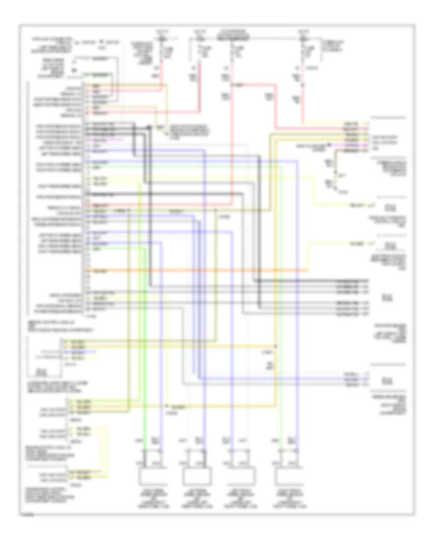
Anti-lock Brakes Wiring Diagram, with Dynamic Stability Control for BMW 540i 1998
List of elements for Anti-lock Brakes Wiring Diagram, with Dynamic Stability Control for BMW 540i 1998:
- (right front side of engine compartment) (cable shoe ground) x1106
- Abs/dsc control module (a65) (right side of engine compartment)
- Body computer system
- Can bus high
- Can bus low
- Can high data
- Can low data
- Data link connector (partial) (left rear side of engine compartment)
- Diagnosis signal txd
- Electronic shock absorber control module (edc) (a80)
- Engine control module (dme) (a6000) (right rear side of engine compartment in e-box)
- Fuse block (in top of glove box)
- Fuse block (right side of right footwell, under carpet)
- Fuse f108 50a
- Fuse f24 5a
- Fuse f30 25a
- Fuse f31 10a
- Ground
- Ground pressure sensor
- Headlight widening control module (a53)
- Hot at all times
- Hot w/engine control module relay energized
- Integrated instrument cluster control module (ike) (a63) (behind instrument cluster)
- Left front speed sens
- Left front speed sensor (b2) (inside left front wheel hub)
- Left rear speed sens
- Left rear speed sensor (b4) (inside left rear wheel hub)
- Nca
- Positive precharge pump
- Power pressure sensor
- Precharge (m118) pump (left side of engine compartment)
- Pressure sensor (b76) (right side of engine compartment)
- Pressure sensor signal
- Red
- Right front speed sens
- Right front speed sensor (b1) (inside right front wheel hub)
- Right rear speed sens
- Right rear speed sensor (b3) (inside right rear wheel hub)
- Rpm rate sensor (b75) (left side of left footwell, under carpet)
- Rpm rate sensor signal
- Rpm rate signal sensor
- Signal rate sens
- Solid state
- Steering angle sensor (r33) (on steering column)
- Terminal 30
- Terminal 87 signal
- Transmission control module (ags) (a7000) (right rear side of engine compartment in e-box)
- Txd
- X10015
- X10114
- X1108
- X1746
- X183
- X18831
- X18832
- X18835
- X18836
- X217
- X27
- X437
- X60002
- X60004
- X70004
 English