ANTI-LOCK BRAKES
Anti-lock Brakes Wiring Diagram (1 of 2) for BMW 550i GT 2014

List of elements for Anti-lock Brakes Wiring Diagram (1 of 2) for BMW 550i GT 2014:
- (behind right front wheel) right front wheel speed sensor
- (or red)
- (top of brake pedal assembly) (hybrid) brake pedal travel sensor
- 13b
- Activation, led function ind
- Brake fluid level switch (left rear engine compt)
- Computer data lines system
- Conditioned wheel spd sig
- Dynamic stability control (dsc) (under right front of vehicle)
- Except hybrid
- Flexray bus sig
- Fuse 30a
- Fuse 50a
- Fuse 5a
- Gnd
- Gnd brk pedal
- Hot at all times
- Hot w/ bi-stable relay energized
- Hybrid
- Junction box (right side of dash)
- Left rear wheel speed sensor (left rear wheel)
- Nca
- Power distribution system
- Rear fuse holder (right side of rear compt)
- Red
- Right rear brake pad wear sensor (behind right rear wheel)
- Right rear wheel speed sensor (right rear wheel)
- Sig brk pedal
- Sig, brk pad wear
- Sply brk pedal
- Sply, terminal 30
- Sply, terminal 30f
- Sw sig
- Wake-up sig, terminal 15
- Wheel spd sig
- Z10 13b (hatchback: right side of cargo area) (sedan: right "c" pillar)
- Z10 4b (left kick panel)
- Z10 9b (left kick panel)
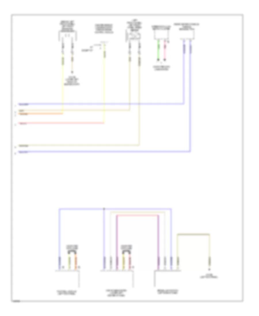
Anti-lock Brakes Wiring Diagram (2 of 2) for BMW 550i GT 2014
List of elements for Anti-lock Brakes Wiring Diagram (2 of 2) for BMW 550i GT 2014:
- (behind left front wheel) left front brake pad wear sensor
- (center rear of luggage compt) parking brake control module
- (left front wheel) left front wheel speed sensor
- (rear center console) parking brake button
- Brake light switch (left side of dash)
- Car access system (lower left center of dash)
- Computer data lines system
- Except gt
- Footwell module (left kick panel)
- Nca
- Pnk
- Steering column switch cluster
- Z10 2b (lower left front of engine compt)
- Z10 9b (left kick panel)