ANTI-LOCK BRAKES
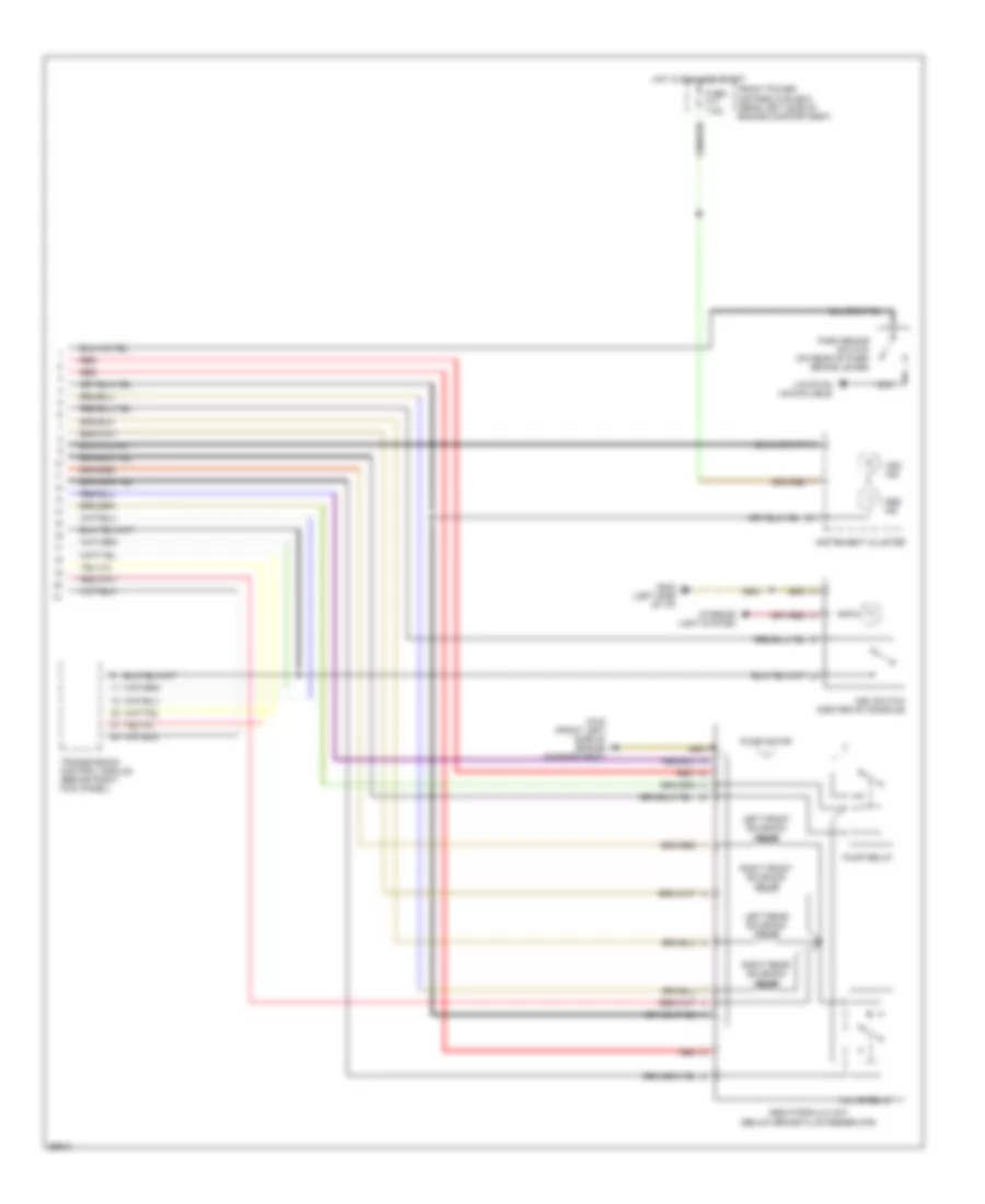
Anti-lock Brake Wiring Diagrams, with Traction Control (1 of 2) for BMW 750iL 1994

List of elements for Anti-lock Brake Wiring Diagrams, with Traction Control (1 of 2) for BMW 750iL 1994:
- 740i/l
- 750il
- B+ junction point (rear left side of engine compartment)
- Cyl 7-12 engine control module relay (right front shock tower) (750il) engine control module relay (right rear of engine compartment) (740i/l)
- Data link connector (left rear of engine compartment) (750il) (right rear of engine compartment) (740i/l)
- Engine controls system
- Front power distribution box (rear left side of engine compartment)
- Fuse f1 15a
- G100 (left front of engine compartment)
- Hot at all times
- Hot in accy, run or start
- Left front abs speed sensor
- Left rear abs speed sensor
- Left rear plunger valve
- Nca
- Pressure sensor/ plunger (left center of engine compartment)
- Recharging valve
- Red
- Right front abs speed sensor
- Right rear abs speed sensor
- Right rear plunger valve
- Slip control module (abs/asc) (right rear side of engine compartment)
- Soild state
- Starting/charging system
- Stop light switch (on brake pedal support bracket)
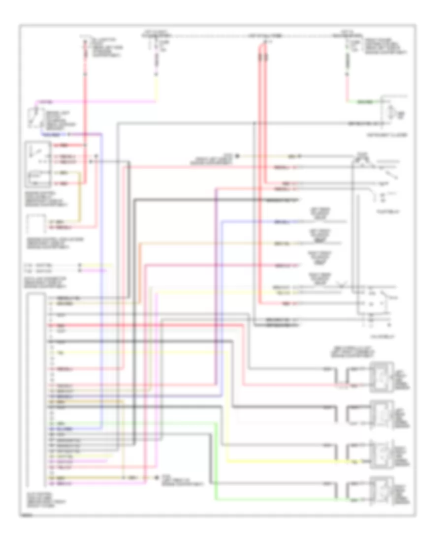
Anti-lock Brake Wiring Diagrams, with Traction Control (2 of 2) for BMW 750iL 1994
List of elements for Anti-lock Brake Wiring Diagrams, with Traction Control (2 of 2) for BMW 750iL 1994:
- Abs hydraulic init (below brake fluid reservoir)
- Abs ind
- Asc ind
- Asc switch (center of console)
- Front power distribution box (rear left side of engine compartment)
- Fuse f17 7.5a
- G100 (front left side of engine compartment)
- G202 (left side of i/p)
- Hot in run and start
- Instrument cluster
- Interior light system
- Left front solenoid valve
- Left rear solenoid valve
- Location unavailable
- Nca
- Park brake switch (on rear of park brake lever)
- Pump motor
- Pump relay
- Red
- Right front solenoid valve
- Right rear solenoid valve
- Transmission control module (behind right kick panel)
- Valve relay
Anti-lock Brake Wiring Diagrams, without Traction Control for BMW 750iL 1994
List of elements for Anti-lock Brake Wiring Diagrams, without Traction Control for BMW 750iL 1994:
- 87a
- Abs hydraulic unit (left front corner of engine compartment)
- Abs ind
- B+ junction point (rear left side of engine compartment)
- Brake light switch (on brake pedal support bracket)
- Data link connector (rear right side of engine compartment)
- Engine control module (dme) (rear right side of engine compartment)
- Engine control module relay (rear right side of engine compartment)
- Front power distribution box (rear left side of engine compartment)
- Fuse f1 15a
- Fuse f17 7.5a
- G100 (front left side of engine compartment)
- G100 (left front of engine compartment)
- Hot at all times
- Hot in accy run and start
- Hot in run and start
- Instrument cluster
- Left front abs speed sensor
- Left front solenoid valve
- Left rear abs speed sensor
- Left rear solenoid valve
- Nca
- Pump motor
- Pump relay
- Red
- Right front abs speed sensor
- Right front solenoid valve
- Right rear abs speed sensor
- Right rear solenoid valve
- Slip control module (abs) (behind right front shock tower)
- Valve relay