ANTI-LOCK BRAKES
Anti-lock Brakes Wiring Diagram for BMW M6 2013
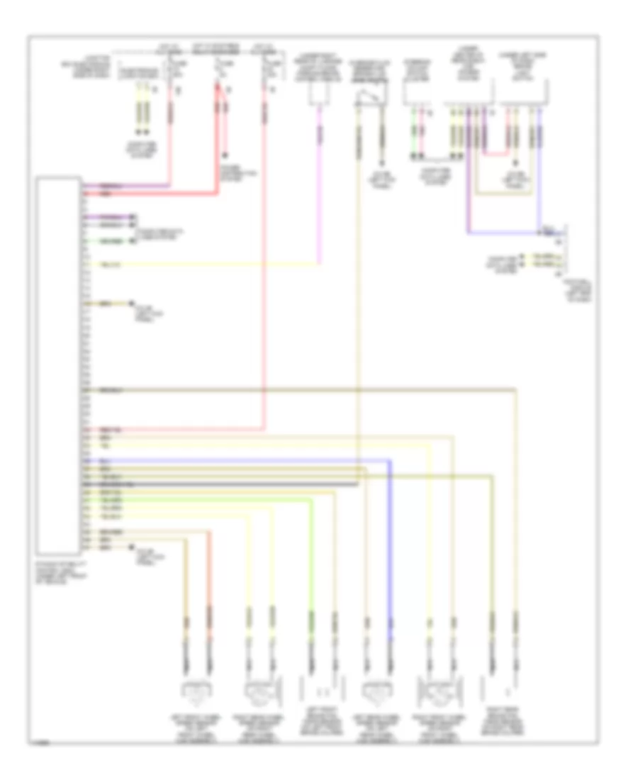
List of elements for Anti-lock Brakes Wiring Diagram for BMW M6 2013:
- (in brake fluid reservoir) brake fluid level switch
- (under center of rear shelf) car access system
- (under left side of dash) brake light switch
- (under right rear of luggage compt floor) parking brake control module
- 13b
- Computer data lines system
- Dynamic stability control (dsc) (under left front of vehicle)
- Electronics junction box
- Footwell module (left end of dash)
- Fuse 30a
- Fuse 50a
- Fuse 5a
- Hot at all times
- Hot w/ bi-stable relay energized
- Junction box electronics (under right side of dash)
- Left front brake pad wear sensor (on left front brake caliper)
- Left front wheel speed sensor (on left front wheel hub assembly)
- Left rear wheel speed sensor (on left rear wheel hub assembly)
- Nca
- Pnk
- Power distribution system
- Red
- Right front wheel speed sensor (on right front wheel hub assembly)
- Right rear brake pad wear sensor (on right rear brake caliper)
- Right rear wheel speed sensor (on right rear wheel hub assembly)
- Steering column switch cluster
- Z10 4b (left kick panel)
- Z10 9b (left kick panel)
 English