ANTI-LOCK BRAKES
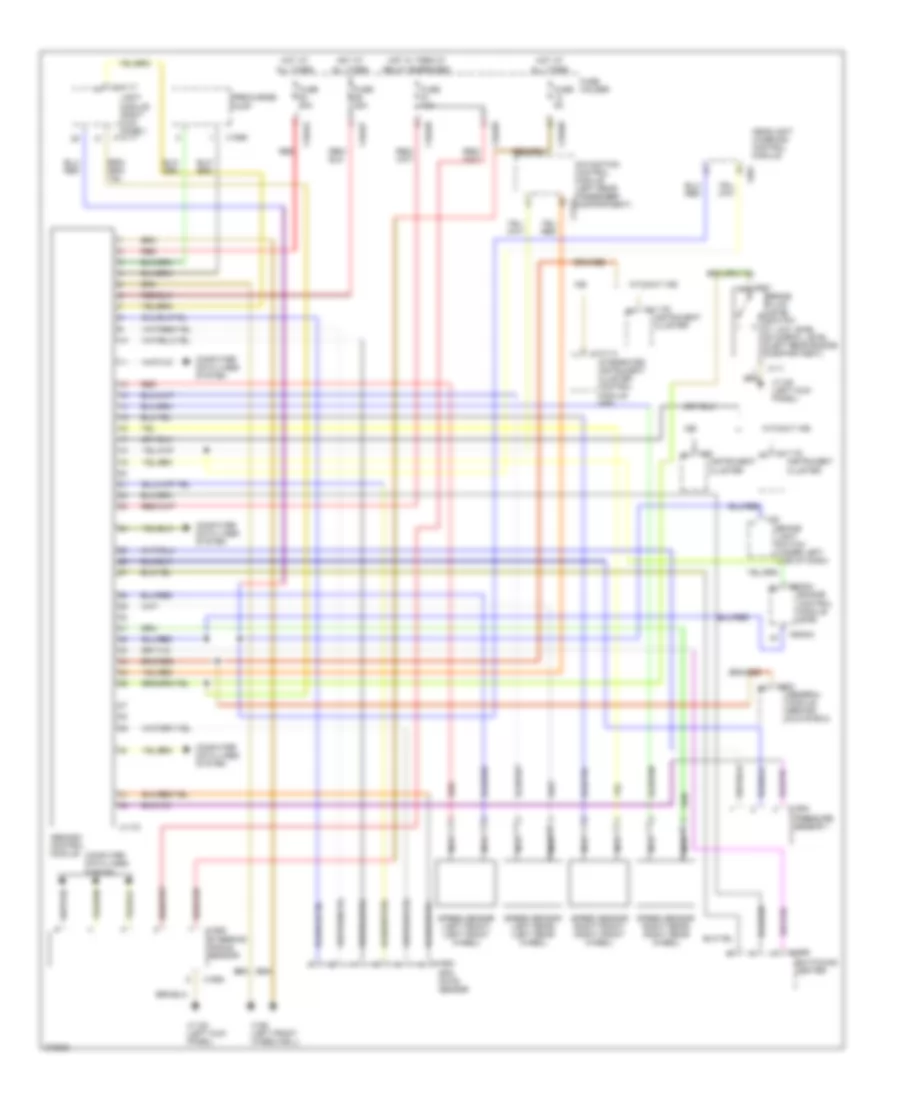
Anti-lock Brakes Wiring Diagram for BMW X5 44i 2001
List of elements for Anti-lock Brakes Wiring Diagram for BMW X5 44i 2001:
- Abs/dsc control module
- Brake fluid level switch 1) low level 2) normal level (left rear engine compartment)
- Brake light switch (under left side of dash)
- Computer data lines system
- Engine control module (dme)
- Fuse 10a
- Fuse 25a
- Fuse 50a
- Fuse 5a
- Fuse holder
- General module (behind glove box)
- Headlight widening control module
- Hot at all times
- Hot w/ term 87 relay energized
- Ike
- Instrument cluster
- Integrated instrument cluster control module (ike)
- Light module (right kick panel)
- Navigation control module (left rear passenger x1312 compartment)
- Nca
- Precharge pump
- Pressure sensor 1
- Red
- Rpm rate sensor
- Speed sensor (left front) (left front wheel)
- Speed sensor (left rear) (left rear wheel)
- Speed sensor (right front) (right front wheel)
- Speed sensor (right rear) (right rear wheel)
- Steering angle sensor
- Switching center
- Without ike
- X10114
- X10117
- X10454
- X10457
- X10458
- X10460
- X1108 (left kick panel)
- X111
- X11175
- X11176
- X1170
- X16
- X165 (left front wheelwell)
- X1653
- X1654
- X1656
- X1658
- X1869
- X253
- X60004
- X78
- X991
 English