ANTI-LOCK BRAKES
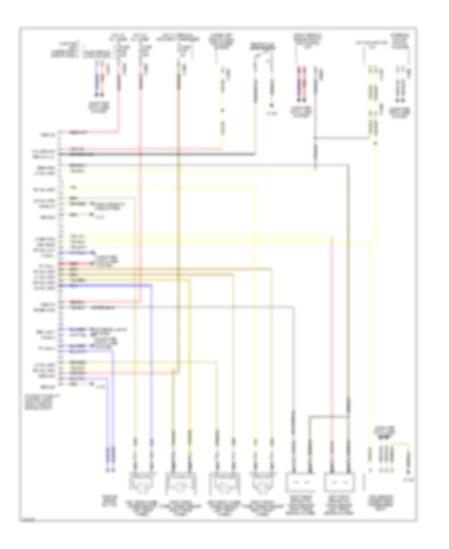
Anti-lock Brakes Wiring Diagram for BMW X5 M 2012
List of elements for Anti-lock Brakes Wiring Diagram for BMW X5 M 2012:
- (right rear of engine compt) dme control unit
- (under left side of dash) car access system
- (w/o navigation) tcu
- Brake fluid level switch
- Brk fld lvl
- Brk light
- Computer data lines system
- Dsc sens
- Dsc sensor (under front passenger's seat)
- Dynamic stability control (dsc) (right side of engine compt)
- Electronics junction box
- Exterior lights system
- F-can h
- F-can l
- Fuse f19 5a
- Fuse f40 30a
- Fuse f46 40a
- Ground
- Hot at all times
- Hot w/ terminal 30g 2 relay energized
- Junction box (under right side of dash)
- Left front brake pad wear sensor (left front brake caliper)
- Left front wheel speed sensor (left front wheel)
- Left rear wheel speed sensor (left rear wheel)
- Lf brk pad
- Lf whl spd
- Lr whl spd
- Nca
- Parking brake button
- Pt can h
- Pt can l
- Red
- Rf whl out
- Rf whl spd
- Right front wheel speed sensor (right front wheel)
- Right rear brake pad wear sensor (right rear brake caliper)
- Right rear wheel speed sensor (right rear wheel)
- Rr brk pad
- Rr whl spd
- Sens gnd
- Steering column switch cluster
- Term 30
- Term 30g
- Wake up
- Whl spd sig
- X11001
- X11004
- X1108
- X13376
- X14087
- X14133
- X14271
- X16818
- X170
- X1880
- X60003
 English