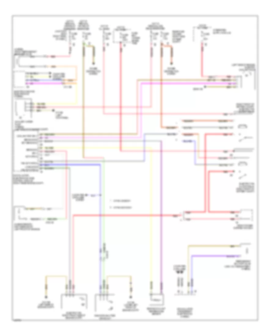
COOLING FAN
Cooling Fan Wiring Diagram for BMW 535i GT xDrive 2014
List of elements for Cooling Fan Wiring Diagram for BMW 535i GT xDrive 2014:
- (hybrid) front refrigerant shut-off valve
- (left side of engine) electric coolant pump
- (right front of battery compt) electric fan cutoff relay
- Accumulator management electronics (hybrid)
- Activation
- Auxiliary water pump (hybrid) (left front of engine compt)
- Bsd bus sig
- Characteristic map thermostat (left front of engine)
- Computer data lines system
- Coolant pmp sply
- Digital motor electronics (dme) control module (right rear engine compt)
- Ect sens gnd
- Electric fan (right front side of engine compt)
- Electric fan cutoff relay (right front of battery compt)
- Electric-machine electronics (hybrid)
- Engine coolant temperature sensor
- Fan activation
- Front power distribution box
- Fuse 100a
- Fuse 10a
- Fuse 50a
- Fuse 5a
- Fuse 60a
- Fuse 7.5a
- Fuse box (under spare tire)
- Hot at all times
- Hot w/ terminal 15n relay energized
- Hot w/ terminal 30b relay energized
- Junction box (right side of dash)
- Lin bus sig
- Nca
- Power distribution system
- Radiator shutter drive unit
- Rear fuse holder (right side of rear compt)
- Red
- Refrigerant shutoff valve (high voltage battery) (hybrid)
- Sens gnd
- Sply
- W/ fan 400/600w
- W/ fan 800/1000w
- X13 12b
- X148 1b
- X671 1b
- X705 1b
- Z10 15b (left rear of engine compt)
- Z10 2b (lower left front of engine compt)
- Z10 5b (left kick panel)
- Z6000 4b
 English