CRUISE CONTROL
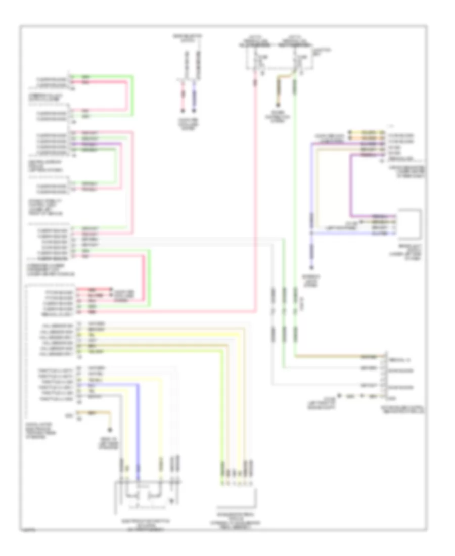
Cruise Control Wiring Diagram for BMW 640i 2014
List of elements for Cruise Control Wiring Diagram for BMW 640i 2014:
- Accelerator pedal module (integral to accelerator pedal assembly)
- Active cruise control (behind front grille)
- Brake light switch (under left side of dash)
- Car access system (under center of rear shelf)
- Central gateway module (left end of dash)
- Computer data lines system
- Digital motor electronics (top right rear of engine)
- Dynamic stability control (dsc) (under left front of vehicle)
- Electromotive throttle actuator (on throttle body)
- Exterior lights system
- Flexray bus sig
- Fuse 10a
- Fuse 5a
- Gear selector switch
- Gnd
- Hall sensor gnd
- Hall sensor sig
- Hall sensor sply
- Hot w/ terminal 15n relay energized
- Hot w/ terminal 30b relay energized
- Integrated chassis management (icm) (under center console)
- Junction box
- K-can bus sig
- Pnk
- Power distribution system
- Pt-can bus sig
- Red
- S-can bus sig
- Steering column switch cluster
- Sw sig
- Terminal 15
- Terminal 30, sply
- Terminal 30b
- Throttle vlv activ
- Throttle vlv gnd
- Throttle vlv sig
- Throttle vlv sply
- X148 1b
- Z10 2b (left front of engine compt)
- Z10 9b (left kick panel)
- Z6000 1b (left rear of engine)
 English