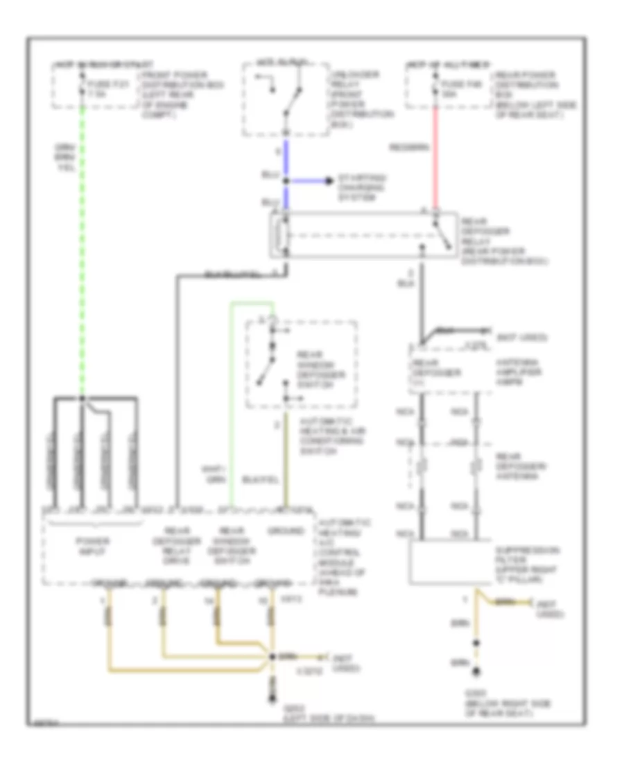
DEFOGGERS
Defogger Wiring Diagram for BMW 750iL 1994
List of elements for Defogger Wiring Diagram for BMW 750iL 1994:
- (not used)
- (not used) x3212
- Antenna amplifier am/fm
- Automatic heating & air conditioning switch
- Automatic heating/ a/c control module (ahead of ihka plenum)
- Front power distribution box (left rear of engine compt)
- Fuse f21 7.5a
- Fuse f46 30a
- G202 (left side of dash)
- G303 (below right side of rear seat)
- Ground
- Hot at all times
- Hot in run
- Hot in run or start
- Nca
- Power input
- Rear defogger (+)
- Rear defogger relay (rear power distribution box)
- Rear defogger relay drive
- Rear defogger/ antenna
- Rear power distribution box (below left side of rear seat)
- Rear window defogger switch
- Starting/ charging system
- Suppression filter (upper right "c" pillar)
- Unloader relay (front power distribution box)
- X379
- X610
- X613
- X614
 English