ELECTRONIC POWER STEERING
Active Power Steering Wiring Diagram for BMW 650i 2013

List of elements for Active Power Steering Wiring Diagram for BMW 650i 2013:
- (left kick panel) z10 5b
- Activation actuator
- Activation srvmtr lock
- Active steering module (under left side of driver's seat)
- Active steering servomotor
- Actuator sig
- Actuator sply
- Central gateway module (left end of dash)
- Electric servomotor lock
- Flexray bus sig
- Fuse 40a
- Fuse 5a
- Gnd
- Hot at all times
- Hot w/ terminal 15n relay energized
- Junction box
- Nca
- Pnk/red
- Power distribution system
- Rear axle king pin inclination control
- Terminal 15 sply
- Terminal 30 sply
- X87 1b
- Z10 50b
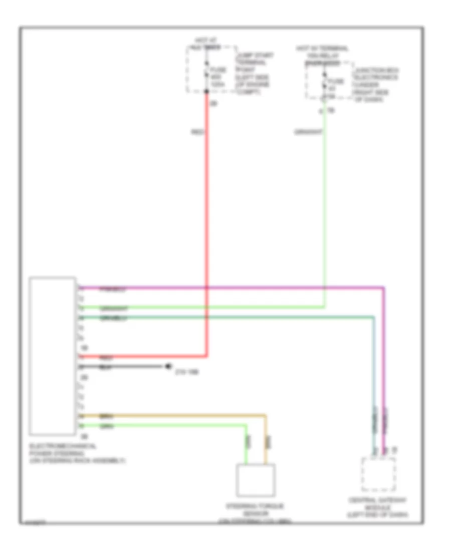
Electromechanical Power Steering Wiring Diagram for BMW 650i 2013
List of elements for Electromechanical Power Steering Wiring Diagram for BMW 650i 2013:
- Central gateway module (left end of dash)
- Electromechanical power steering (on steering rack assembly)
- Fuse 125a
- Fuse 5a
- Hot at all times
- Hot w/ terminal 15n relay energized
- Jump start terminal point (left side of engine compt)
- Junction box electronics (under right side of dash)
- Red
- Steering-torque sensor (on steering column)
- Z10 19b
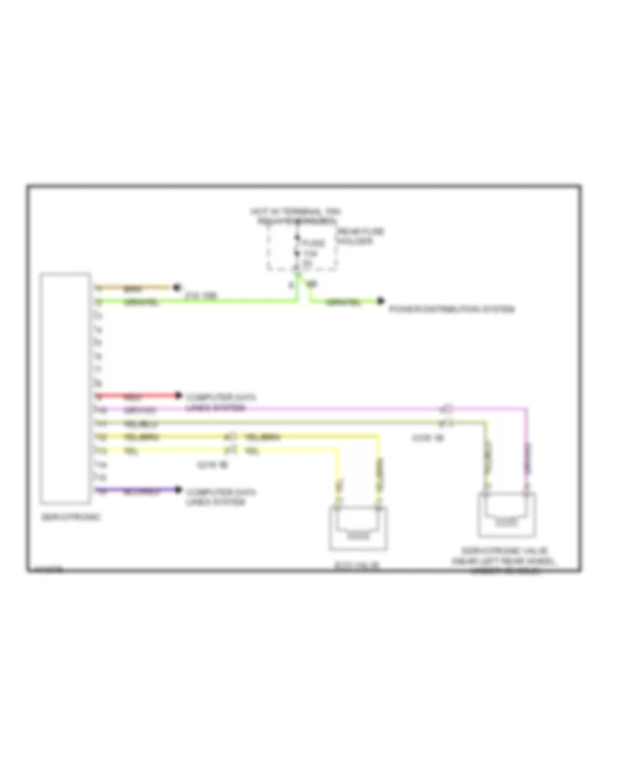
Servotronic Wiring Diagram for BMW 650i 2013
List of elements for Servotronic Wiring Diagram for BMW 650i 2013:
- Computer data lines system
- Eco valve
- Fuse 5a
- Hot w/ terminal 15n relay energized
- Power distribution system
- Rear fuse holder
- Red
- Servotronic
- Servotronic valve (near left rear wheel, under vehicle)
- X219 1b
- X335 1b
- Z10 16b