ELECTRONIC POWER STEERING
Active Power Steering Wiring Diagram for BMW 650i Gran Coupe xDrive 2014

List of elements for Active Power Steering Wiring Diagram for BMW 650i Gran Coupe xDrive 2014:
- (left kick panel) z10 5b
- Activation actuator
- Activation srvmtr lock
- Active steering module (under left side of driver's seat)
- Active steering servomotor
- Actuator sig
- Actuator sply
- Central gateway module (left end of dash)
- Electric servomotor lock
- Flexray bus sig
- Fuse 40a
- Fuse 5a
- Gnd
- Hot at all times
- Hot w/ terminal 15n relay energized
- Junction box
- Nca
- Pnk/red
- Power distribution system
- Rear axle king pin inclination control
- Terminal 15 sply
- Terminal 30 sply
- X87 1b
- Z10 50b
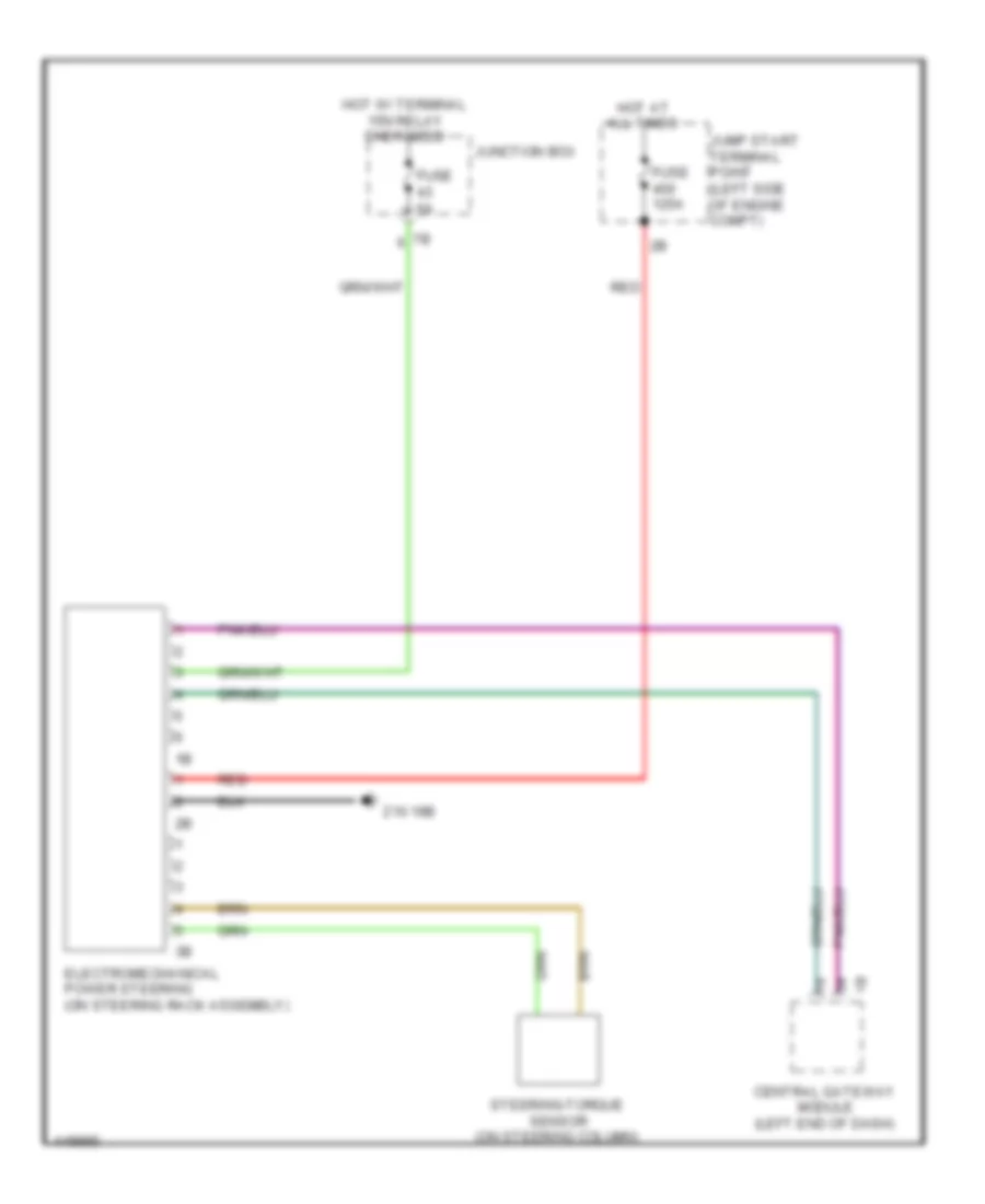
Electromechanical Power Steering Wiring Diagram for BMW 650i Gran Coupe xDrive 2014
List of elements for Electromechanical Power Steering Wiring Diagram for BMW 650i Gran Coupe xDrive 2014:
- Central gateway module (left end of dash)
- Electromechanical power steering (on steering rack assembly)
- Fuse 125a
- Fuse 5a
- Hot at all times
- Hot w/ terminal 15n relay energized
- Jump start terminal point (left side of engine compt)
- Junction box
- Red
- Steering-torque sensor (on steering column)
- Z10 19b
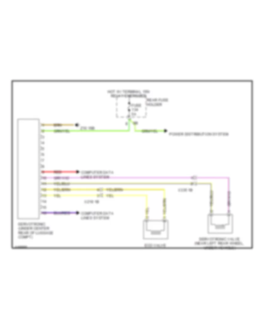
Servotronic Wiring Diagram for BMW 650i Gran Coupe xDrive 2014
List of elements for Servotronic Wiring Diagram for BMW 650i Gran Coupe xDrive 2014:
- Computer data lines system
- Eco valve
- Fuse 5a
- Hot w/ terminal 15n relay energized
- Power distribution system
- Rear fuse holder
- Red
- Servotronic (under center rear of luggage compt)
- Servotronic valve (near left rear wheel, under vehicle)
- X219 1b
- X335 1b
- Z10 16b