ELECTRONIC SUSPENSION
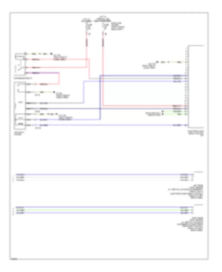
Air Suspension Wiring Diagram (1 of 2) for BMW M5 2014

List of elements for Air Suspension Wiring Diagram (1 of 2) for BMW M5 2014:
- (behind right front wheel) (w/ vertical dynamics management) right front level sensor
- (left end of dash) central gateway module
- (right kick panel) z10 11b
- (under front of center console) z10 10b
- 2.0l turbo & 4.4l turbo m5
- 3.0l turbo & 3.0l turbo hybrid
- 3.0l turbo diesel & 4.4 turbo except m5
- Center console operating unit
- Computer data lines system
- Digital motor electronics (dme) control module (except 3.0l turbo diesel) digital diesel electronics (3.0l turbo diesel) (2.0l turbo: top rear of engine) (4.4l turbo: right rear engine compt)
- Except m5
- Fuse 5a
- Hot w/ terminal 30b relay energized
- Integrated chassis management (under center console)
- Junction box (right side of dash)
- Left front level sensor (w/ vertical dynamics management & xenon light)
- Pnk
- Steering column switch cluster
Air Suspension Wiring Diagram (2 of 2) for BMW M5 2014
List of elements for Air Suspension Wiring Diagram (2 of 2) for BMW M5 2014:
- Compressor relay
- Computer data lines system
- Electronic ride height control (gt)
- Fuse 40a
- Fuse 5a
- Hot at all times
- Hot w/ terminal 30b relay energized
- Left rear level sensor (w/ vertical dynamics management, xenon light & electronic ride height control) (front of left rear wheel)
- M6 1b
- M6 2b
- Nca
- Rear fuse holder (right side of rear compt)
- Right rear level sensor (w/ vertical dynamics management & electronic ride height control) (front of right rear wheel)
- Y25 1b
- Z10 17b (right side of cargo area)
- Z10 8b (right side of cargo area)
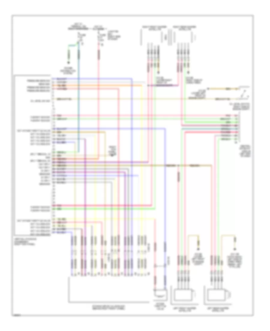
Dynamic Drive Suspension Wiring Diagram for BMW M5 2014
List of elements for Dynamic Drive Suspension Wiring Diagram for BMW M5 2014:
- (right kick panel) z10 6b
- 5v sply
- Act intake throttle valve
- Act valve block
- Central gateway module (left end of dash)
- Dynamic drive valve block (behind right front wheel)
- Flexray bus sig
- Fuse 30a
- Fuse 5a
- Gnd
- Hot at all times
- Hot w/ terminal 15n relay energized
- Intake throttle valve
- Junction box (right side of dash)
- Left front damper satellite
- Left rear damper satellite
- Nca
- Oil level sw sig
- Oil level switch (right side of engine compt)
- Pnk
- Pnk/red
- Power distribution system
- Pressure sens sig
- Right front damper satellite
- Right rear damper satellite
- Sens gnd
- Sply terminal 15
- Sply terminal 30
- Vertical dynamics management (right kick panel)
- Volt sply
- X158 1b
- X159 1b
- X219 1b
- Z10 14b (hatch back: left side of cargo area) (sedan: left "c" pillar)
- Z10 2b (lower left front of engine compt)
- Z10 3b (lower right front of engine compt)
- Z10 8b (right side of cargo area)
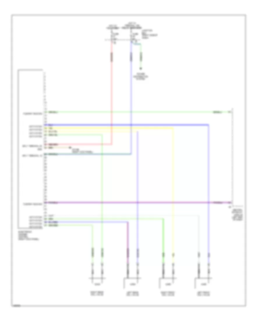
Electronic Damper Control Wiring Diagram for BMW M5 2014
List of elements for Electronic Damper Control Wiring Diagram for BMW M5 2014:
- Activation
- Central gateway module (left end of dash)
- Electronic damper control (right kick panel)
- Flexray bus sig
- Fuse 30a
- Fuse 5a
- Gnd
- Hot at all times
- Hot w/ terminal 15n relay energized
- Junction box (right side of dash)
- Left front coil valve
- Left rear coil valve
- Nca
- Power distribution system
- Right front coil valve
- Right rear coil valve
- Sply terminal 15
- Sply terminal 30
- Z10 6b (right kick panel)