ENGINE PERFORMANCE
4.0L
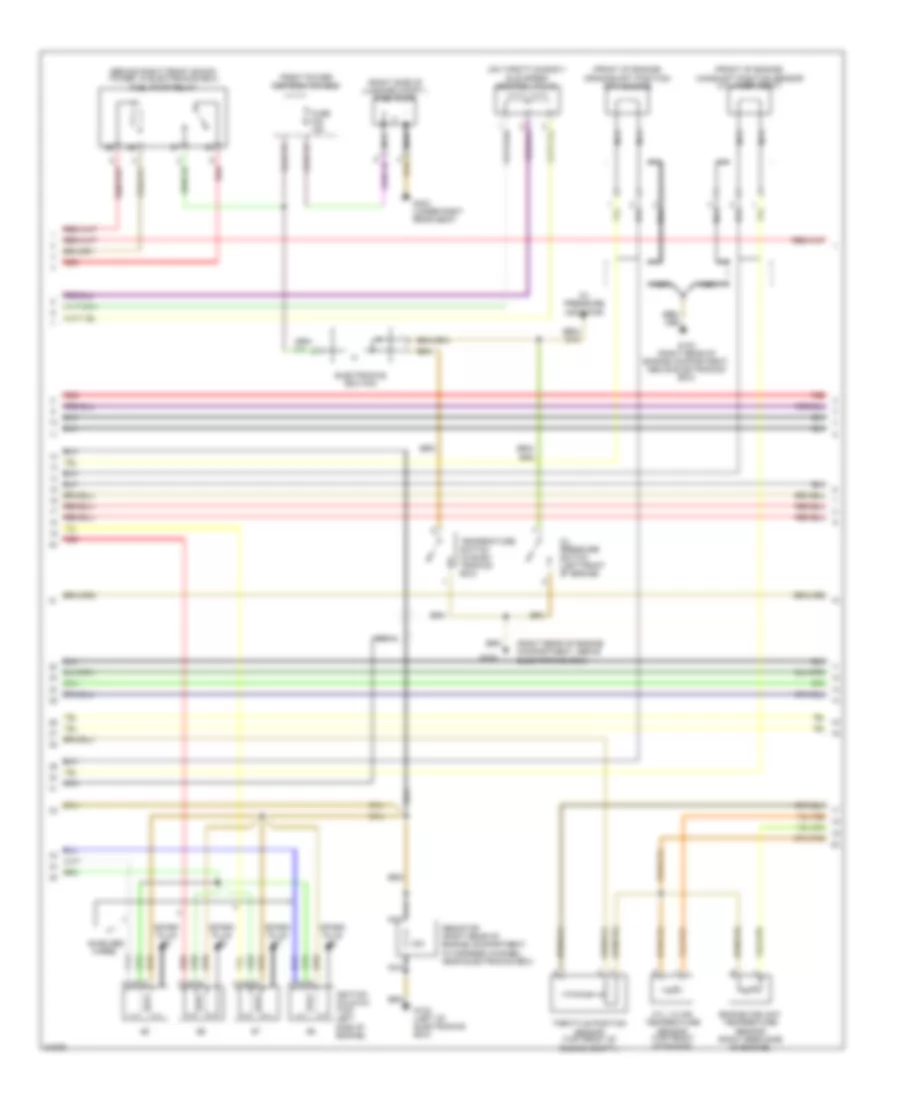
4.0L, Engine Performance Wiring Diagrams (1 of 3) for BMW 540i 1995

List of elements for 4.0L, Engine Performance Wiring Diagrams (1 of 3) for BMW 540i 1995:
- "check eng" ind
- "check engine" ind
- (behind right front shock tower, in electronics box) engine control module relay
- (behind right front shock tower, in electronics box) transmission control module
- (right rear of engine compartment, above electronics box)
- (right rear of engine compt., above e-box) g103
- 530i/it only
- A/c compressor sig
- Air flow sig (hlm)
- B+ junction point (behind right front shock tower, in electronics box)
- Camshaft sens gnd
- Camshaft sig (nwg)
- Carbon canister (behind left fog light)
- Close zwd
- Comp- ressor control relay
- Crankshaft sens gnd
- Crankshaft sig (kwg)
- Cyl #1 ign sig
- Cyl #2 ign sig
- Cyl #3 ign sig
- Cyl #4 ign sig
- Cyl #5 ign sig
- Cyl #6 ign sig
- Cyl #7 ign sig
- Cyl #8 ign sig
- Cylinders 1-4 ho2s
- Cylinders 5-8 ho2s
- Ecm relay ctrl
- Ecm relay sig
- Elc/sh/sens gnd
- Engine rpm sig (td)
- Engine speed in
- Evap emiss sig
- Fuel cons sig (kva)
- Fuel consum in
- Fuel inj #1
- Fuel inj #2
- Fuel inj #3
- Fuel inj #4
- Fuel inj #5
- Fuel inj #6
- Fuel inj #7
- Fuel inj #8
- Fuel inj gnd
- Fuel injection valves
- Fuel pump relay
- G103
- Gnd
- Ho2s relay ctrl
- Hot at all times
- Ign gnd
- Ign monitor
- Ign monitor gnd
- Ign-run/start (15)
- Ignition coils 1-4 (top right side of engine)
- Instrument cluster
- Maf sens gnd (hlm)
- Mass air flow sensor (right front of engine)
- Nca
- Open zwd
- Powertrain control module (dme) (behind right front shock tower, in electronics box)
- Red
- Sec air pump
- Shielded
- Slip control module
- Spark plug #1
- Spark plug #2
- Spark plug #3
- Spark plug #4
- Speed sig
- Throttle angle
- Vehicle speed out
- Wires
- X16
- X502
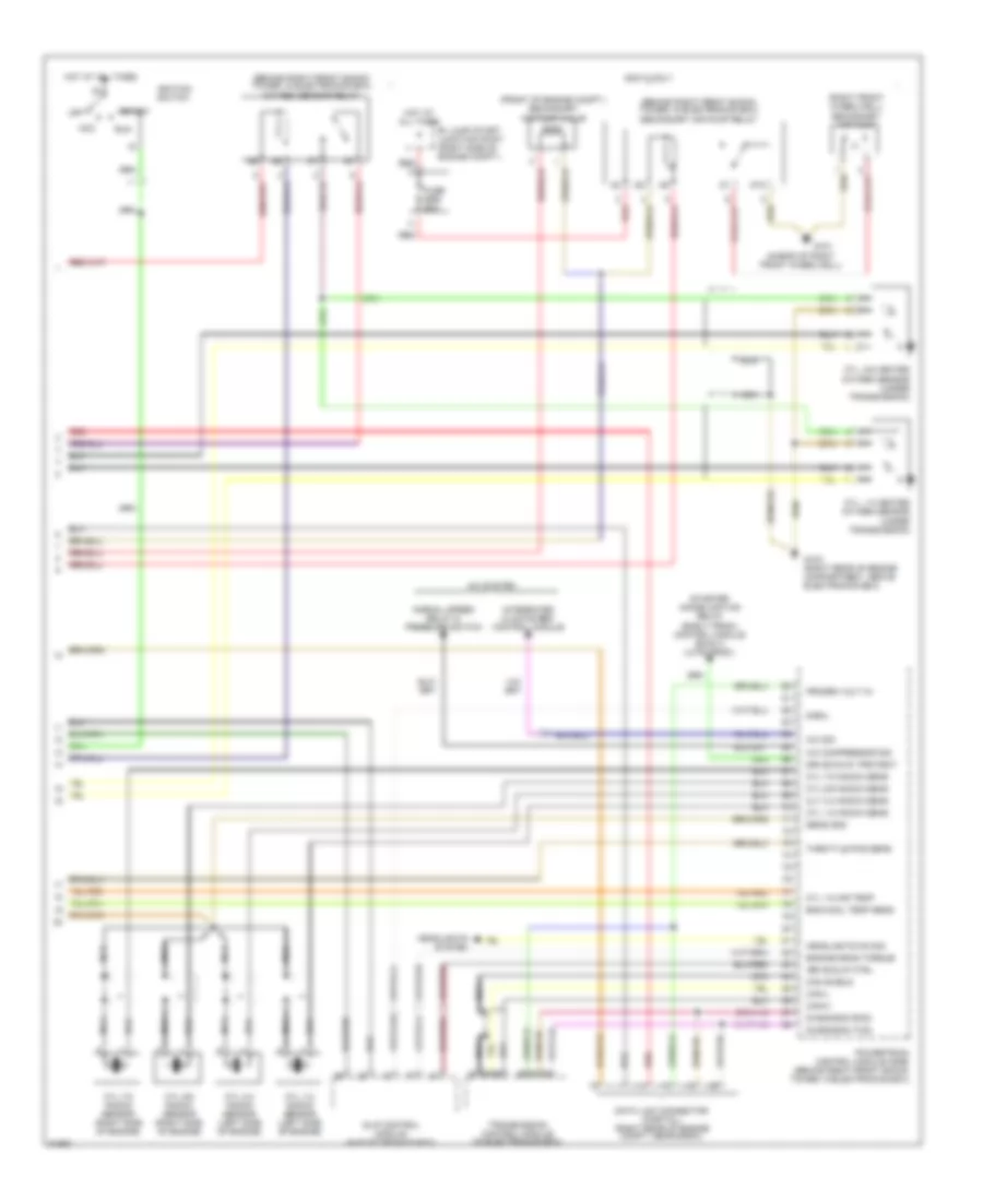
4.0L, Engine Performance Wiring Diagrams (2 of 3) for BMW 540i 1995
List of elements for 4.0L, Engine Performance Wiring Diagrams (2 of 3) for BMW 540i 1995:
- (behind right front shock tower, in electronics box) fuel pump relay
- (front of engine) camshaft position sensor (cylinder ident)
- (front of engine) crankshaft position/ rpm sensor
- (on throttle body) idle speed control valve
- (right rear of engine compartment, above electronics box)
- (right side of luggage compt.) fuel pump
- Cyl 1-8 air temperature sensor (top front of engine)
- Electronics box fan
- Engine coolant temperature sensor (right rear side of engine)
- Front power distribution box
- Fuse f23 15a
- G103
- G103 (right rear of engine compartment, above electronics box)
- G123 (left of electronics box)
- G303 (under right rear seat)
- Ignition coils 5-8 (top left side of engine)
- Nca
- Oil pressure indicator
- Oil pressure switch (left front of engine)
- Red
- Resistor (right rear of engine compartment, in harness channel, near electronics box)
- Shielded
- Spark plug #5
- Spark plug #6
- Spark plug #7
- Spark plug #8
- Temperature switch (in elec- tronics box)
- Throttle position sensor (top front of engine compt.)
- Wires
4.0L, Engine Performance Wiring Diagrams (3 of 3) for BMW 540i 1995
List of elements for 4.0L, Engine Performance Wiring Diagrams (3 of 3) for BMW 540i 1995:
- (ahead of right front wheelwell)
- (behind right front shock tower, in electronics box) oxygen sensor relay
- (behind right front shock tower, in electronics box) secondary air pump relay
- (front of engine compt.) secondary air pump valve
- (right front wheelwell) secondary air pump
- 530i/it only
- 87a
- A/c compressor sig
- A/c sig
- A/c system
- Acc
- B+ jump start junction point (right side of engine compt.)
- Can shield
- Can-h
- Can-l
- Cly 3-4 knock sens
- Cyl 1-2 knock sens
- Cyl 1-2 knock sensor (left side of engine)
- Cyl 1-8 air temp
- Cyl 3-4 knock sensor (left side of engine)
- Cyl 5-6 knock sens
- Cyl 5-6 knock sensor (right side of engine)
- Cyl 7-8 knock sens
- Cyl 7-8 knock sensor (right side of engine)
- Cyl. 1-4 heated oxygen sensor (under transmission)
- Cyl. 5-8 heated oxygen sensor (under transmission)
- Data link connector (partial) (right rear of engine compt, near e-box)
- Diagnosis (rxd)
- Diagnosis (txd)
- Drive slip ctrl
- Drive-away protect
- Eng cool temp sens
- Engine drag torque
- Fuse 50a
- G101
- G103 (right rear of engine compartment, above electronics box)
- Headlights on sig
- Headlights system
- Hot at all times
- Ignition switch
- Integrated climate reg. control module
- Nca
- Normal speed relay & pressure switch
- Off
- Powertrain control module (dme) (behind right front shock tower, in electronics box)
- Progrm volt in
- Red
- Run
- S-eml
- Sens gnd
- Slip control module (in electronics box)
- Start
- Starter immobilization relay (early prod.) control module (ews ii) (late prod.)
- Throttle pos sens
- Transmission control module (in electronics box)