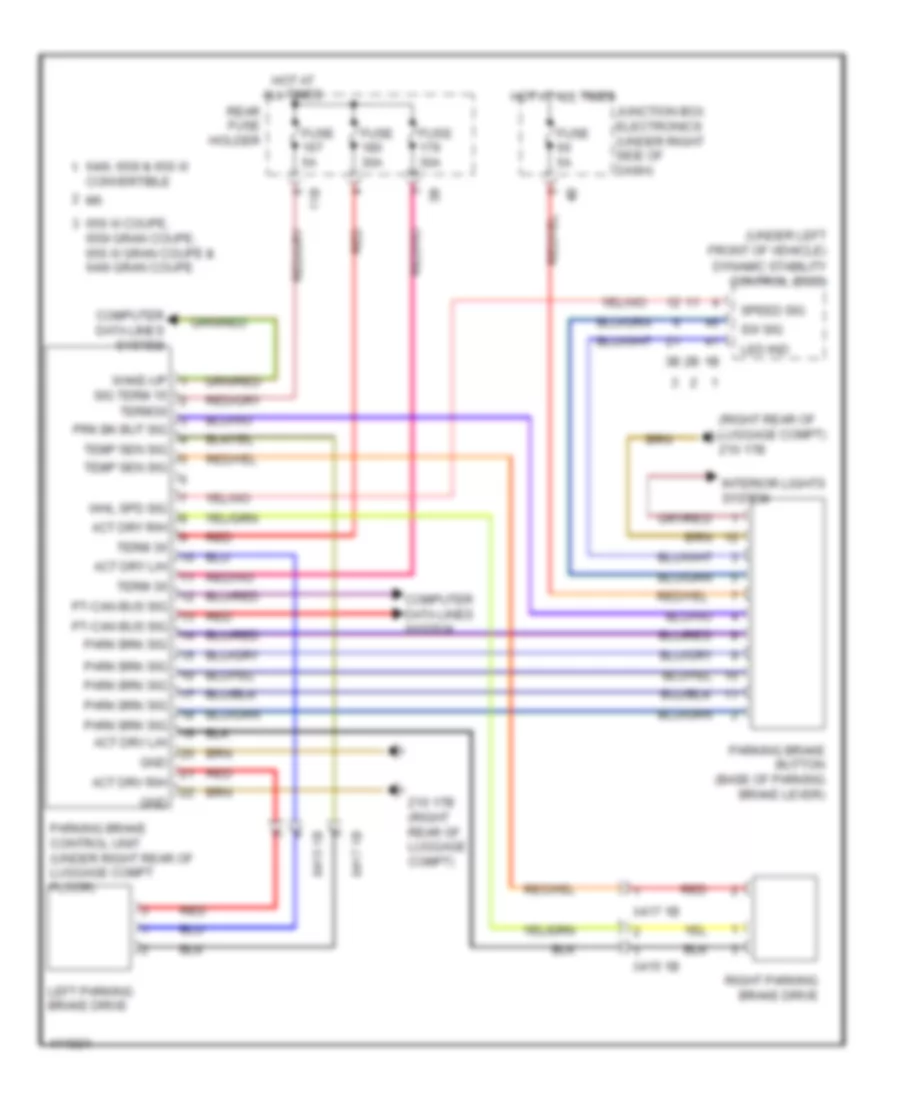
SHIFT INTERLOCK
Shift Interlock Wiring Diagram for BMW 640i Gran Coupe 2013
List of elements for Shift Interlock Wiring Diagram for BMW 640i Gran Coupe 2013:
- (right rear of luggage compt) z10 17b
- (under left front of vehicle)
- 11b
- 640i, 650i & 650 xi
- 650 xi coupe, 650i gran coupe, 650 xi gran coupe & 640i gran coupe
- Act drv l/h
- Act drv r/h
- Act dry l/h
- Act dry r/h
- Computer data lines system
- Convertible
- Dynamic stability control (dsc)
- Fuse 30a
- Fuse 5a
- Gnd
- Hot at all times
- Interior lights system
- Junction box electronics (under right side of dash)
- Led ind
- Left parking brake drive
- Park brk sig
- Parking brake button (base of parking brake lever)
- Parking brake control unit (under right rear of luggage compt floor)
- Prk bk but sig
- Pt-can bus sig
- Rear fuse holder
- Red
- Right parking brake drive
- Sig term 15
- Speed sig
- Sw sig
- Temp sen sig
- Term 30
- Term30
- Wake-up
- Whl spd sig
- X415 1b
- X417 1b
- Z10 17b (right rear of luggage compt)
 English