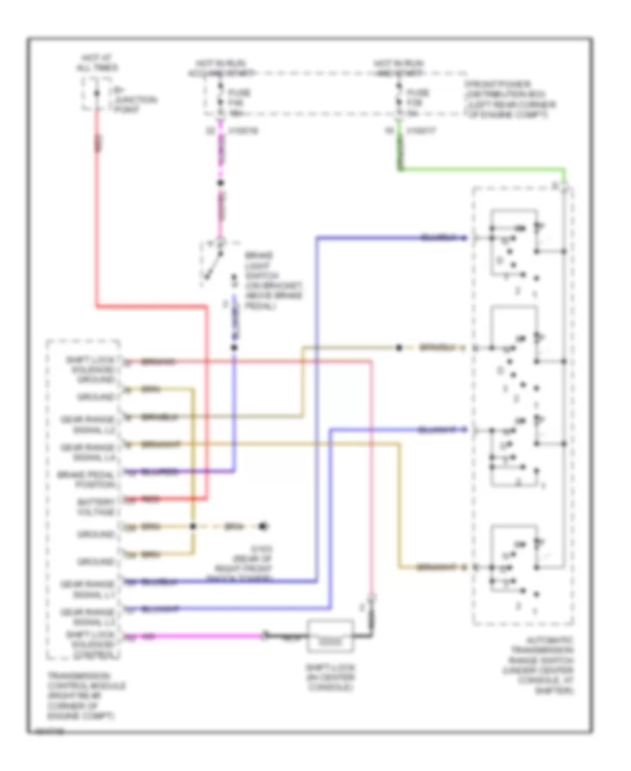
AUTOMOTIVE ELECTRICIANS PORTAL

SHIFT INTERLOCKS – BMW 318ti 1998 – SYSTEM WIRING DIAGRAMS

SHIFT INTERLOCKS

Shift Interlock Wiring Diagram for BMW 318ti 1998

Shift Interlock Wiring Diagram for BMW 318ti 1998 https://portal-diagnostov.com/license.html
https://portal-diagnostov.com/license.html Automotive Electricians Portal FZCO Automotive Electricians Portal FZCO
Get access to all wiring diagrams of the carDownload PDF file

List of elements for Shift Interlock Wiring Diagram for BMW 318ti 1998:

  • Automatic transmission range switch (under center console, at shifter)
  • B+ junction point
  • Battery voltage
  • Brake light switch (on bracket, above brake pedal)
  • Brake pedal position
  • Front power distribution box (left rear corner of engine compt)
  • Fuse f28 5a
  • Fuse f46 15a
  • G103 (rear of right front shock tower)
  • Gear range signal l1
  • Gear range signal l2
  • Gear range signal l3
  • Gear range signal l4
  • Ground
  • Hot at all times
  • Hot in run acc and start
  • Hot in run and start
  • Nca
  • Red
  • Shift lock solenoid control
  • Shift lock solenoid ground
  • Shift-lock (in center console)
  • Transmission control module (right rear corner of engine compt)
  • X10017
  • X10018