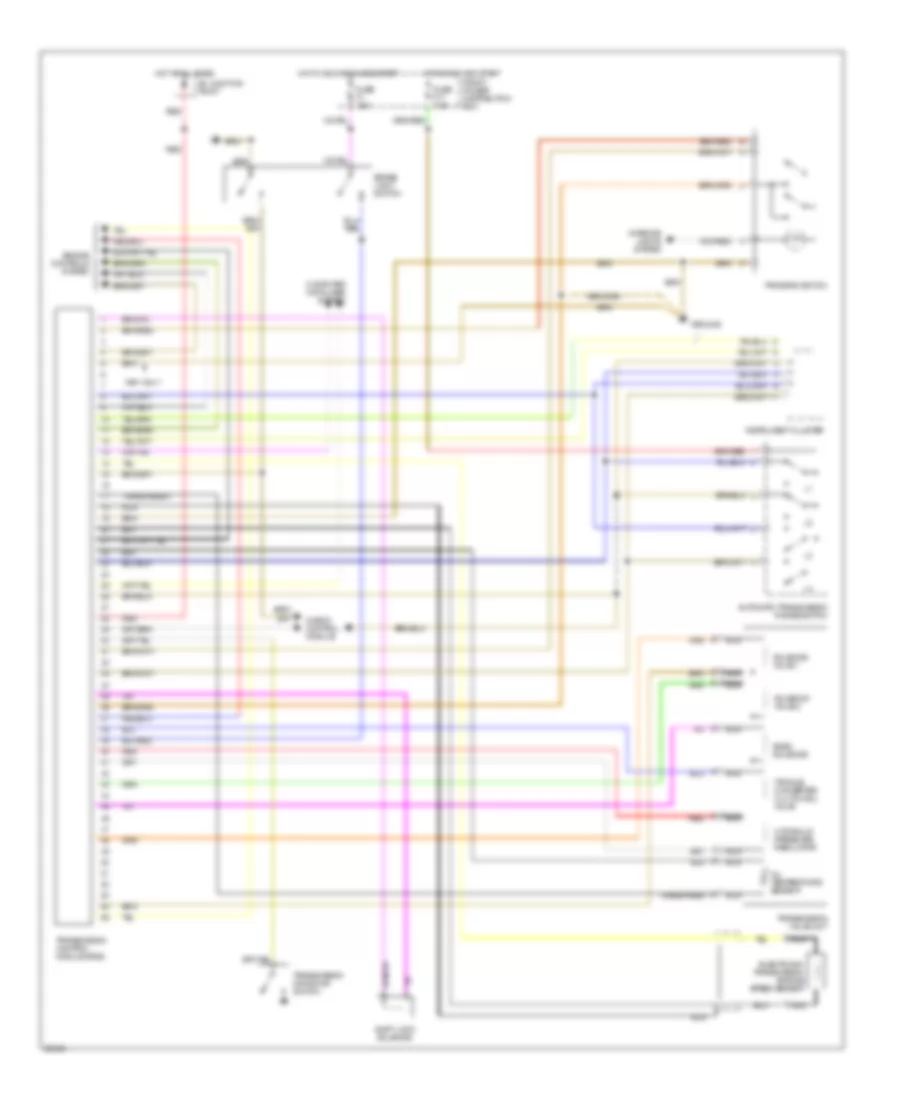
AUTOMOTIVE ELECTRICIANS PORTAL

TRANSMISSION – BMW 525i 1993 – SYSTEM WIRING DIAGRAMS

TRANSMISSION

Transmission Wiring Diagram for BMW 525i 1993

Transmission Wiring Diagram for BMW 525i 1993 https://portal-diagnostov.com/license.html
https://portal-diagnostov.com/license.html Automotive Electricians Portal FZCO Automotive Electricians Portal FZCO
Download PDF file

List of elements for Transmission Wiring Diagram for BMW 525i 1993:

  • A-mode ind
  • A/c comp. ctrl.
  • A/c on
  • Auto mode
  • Automatic transmission range switch (front of gearshift selector)
  • B+ junction point (right rear side of engine compartment in e-box)
  • Band sol (+)
  • Band solenoid
  • Batt volt
  • Bk pdl posit.
  • Bk sw test
  • Brake light switch (on brake pedal support bracket)
  • C 1995 vftc
  • Check control module
  • Clr
  • Crank rpm sig.
  • Cruise control module (tempomat) (behind left front of i/p)
  • Data link connector (left rear side of engine compartment, right of left side shock tower)
  • Drive range p/n
  • Egs a4s 310r
  • Electronic transmission engine speed sensor (egs) (under center of car)
  • Engine control module (dme) (right rear side of engine compartment in e-box)
  • Engine control module relay (right rear side of engine compartment in e-box)
  • Engine controls system
  • Fault ind sig
  • Front power distribution box (left rear side of engine compartment)
  • Fuel consumption
  • Fuse f1 15a
  • Fuse f17 7.5a
  • G105 (right rear side of engine compartment)
  • G202 (left side of i/p)
  • Gnd
  • Gr rng l1
  • Gr rng l2
  • Gr rng l3
  • Gr rng l4
  • Gr rng sig l1
  • Gr rng sig l2
  • Gr rng sig l3
  • Gr rng sig l4
  • Hot at all times
  • Hot in accy, run & start
  • Hot in run & start
  • Hyd ctrl (+)
  • Hyd ctrl (-)
  • Hydraulic pressure regulator
  • Ig timing int
  • Ign timing int.
  • Instrument cluster
  • Interior lights system
  • Kick down switch (right side of left footwell)
  • Kick-dn sig
  • Man mode ind
  • Man mode sig
  • Nca
  • Oil temp sig
  • Oil temperature sensor
  • On-board computer
  • Out spd (+)
  • Out spd (-)
  • Program switch
  • Red
  • Rpm spd sig
  • Rxd data lk
  • Shield gnd
  • Shift lk gnd
  • Shift lk sol
  • Shift lock (below center console front of gearshift selector)
  • Sol val 1 (+)
  • Sol val 2 (+)
  • Sol val ctrl
  • Solenoid valve 1
  • Solenoid valve 2
  • Starter relay (left rear side of engine compartment in front power distribution box)
  • Tcc sol ctrl
  • Throttle val posit.
  • Ti sig (fl)
  • Ti sig (fuel econ.)
  • Torque converter clutch solenoid valve
  • Tp sig
  • Trans mode
  • Transmission control module (egs) (right rear side of engine engine compartment in e-box)
  • Transmission valve unit (in transmission)
  • Txd data lk
  • X16
  • X502

Transmission Wiring Diagram, 4 Speed with Overdrive for BMW 525i 1993

Transmission Wiring Diagram, 4 Speed with Overdrive for BMW 525i 1993 https://portal-diagnostov.com/license.html
https://portal-diagnostov.com/license.html Automotive Electricians Portal FZCO Automotive Electricians Portal FZCO
Get access to all wiring diagrams of the carDownload PDF file

List of elements for Transmission Wiring Diagram, 4 Speed with Overdrive for BMW 525i 1993:

  • 1991 only
  • Automatic transmission range switch
  • B+ junction point
  • Band solenoid
  • Brake light switch
  • Check control module
  • Computer data lines system
  • Electronic transmission engine speed sensor
  • Engine controls system
  • Front power distribution box
  • Fuse f1 15a
  • Fuse f17 7.5a
  • Ground
  • Hot at all times
  • Hot in accy, run and start
  • Hot in run and start
  • Hydraulic pressure regulator
  • Instrument cluster
  • Interior lights system
  • Nca
  • Oil temperature sensor
  • Program switch
  • Red
  • Shift lock solenoid
  • Solenoid valve 1
  • Solenoid valve 2
  • Torque converter clutch sol valve
  • Transmission control module (egs)
  • Transmission kickdown switch
  • Transmission valve unit
  • Transparent