TRANSMISSION
A/T Wiring Diagram for BMW 640i 2014

List of elements for A/T Wiring Diagram for BMW 640i 2014:
- (or red)
- Computer data lines system
- Electronic transmission control (4.4l turbo) automatic transmission (3.0l turbo)
- Fuse 10a
- Fuse 7.5a
- Gear selector switch
- Gnd
- Hot w/ terminal 30b relay energized
- Junction box (under right side of dash)
- Left shift paddle
- Nca
- Pt-can
- Pt-can bus sig
- Pwr sply
- Red
- Right shift paddle
- Steering column switch cluster
- Wake-up sig
- Wakeup sig
- X13 11b
- Z1 8b
- Z10 6b (right kick panel)
- Z6000 5b (4.4l turbo) z6000 1b (3.0l turbo) (3.0l turbo: left rear of engine)
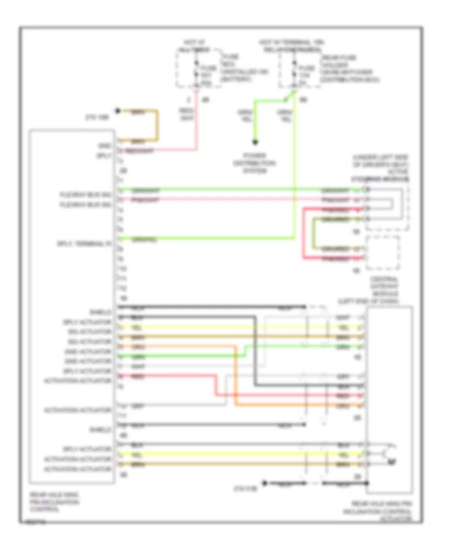
Rear Axle Wiring Diagram for BMW 640i 2014
List of elements for Rear Axle Wiring Diagram for BMW 640i 2014:
- (under left side of driver's seat) active steering module
- Activation actuator
- Central gateway module (left end of dash)
- Flexray bus sig
- Fuse 5a
- Fuse 60a
- Fuse box (installed on battery)
- Gnd
- Gnd actuator
- Hot at all times
- Hot w/ terminal 15n relay energized
- Nca
- Pnk/red
- Power distribution system
- Rear axle king pin inclination control
- Rear axle king pin inclination control actuator
- Rear fuse holder (in rear power distribution box)
- Red
- Shield
- Sig actuator
- Sply
- Sply actuator
- Sply, terminal15
- Z10 16b
- Z10 51b
 English