AIR CONDITIONING
Automatic A/C Wiring Diagram (1 of 2) for Saab 9-5 Aero 2004

List of elements for Automatic A/C Wiring Diagram (1 of 2) for Saab 9-5 Aero 2004:
- (behind right headlamp) g31
- (center of dash, behind radio) g41p
- (on left end of cylinder head)
- A red
- A/c compressor
- A/c compressor relay (on engine bay main relay board)
- A/c pressure sensor (on bottom right side of condenser)
- Acc control module (in center of dash)
- Air distribution damper motor
- Blend air flap motor (left) (on left end of heating & ventilation unit)
- Blend air flap motor (right) (on right end of heating & ventilation unit)
- C15-2
- C160-17
- C161-17
- C30-2
- C31-16
- C35
- C36
- C37
- C59-1
- C60-1
- C63
- C64
- C65
- C66
- C67
- C70-1
- C72
- C73
- C74
- C75
- C76
- C81
- C82
- C83
- C84
- C85
- C86
- C87
- C88
- C89
- C90
- C91
- C92
- C93
- C94
- C95
- Cabin air temperature sensor
- Computer data lines system
- Coolant temperature sensor
- Dashboard main fuse board (behind left end of dash)
- Dice control module (above dashboard main relay board)
- E18
- E31-10
- E35
- E69
- E70
- E71
- Engine bay main fuse board (behind battery)
- Fuse 10a
- Fuse 15a
- Fuse 30a
- Fuse 7.5a
- G41p (center of dash, behind radio)
- H2-2
- Hot at all times
- Hot in on
- Hot in on or start
- Hot w/main relay energized
- Nca
- Recirculation flap motor (behind right side of dash, next to ventilation fan motor)
- Red
- Solar sensor (on top center of dash)
- Solid state
- Trionic control module (in right rear of engine compartment)
- Ventilation fan control unit (on driver's side of heating & ventilation unit, near firewall)
- Ventilation fan motor (in top of heating & ventilation unit)
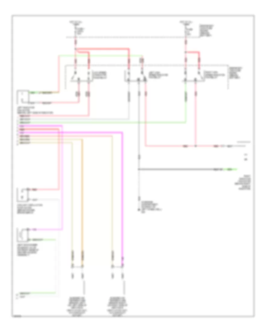
Automatic A/C Wiring Diagram (2 of 2) for Saab 9-5 Aero 2004
List of elements for Automatic A/C Wiring Diagram (2 of 2) for Saab 9-5 Aero 2004:
- (in engine compartment, on front of left wheelwell) g30
- 87a
- Blended air temperature sensor (left) (on left side of heating & ventilation unit, in floor duct outlet)
- Blended air temperature sensor (right) (on right side of heating & ventilation unit, in floor duct outlet)
- Coolant circulation pump motor (behind power brake servo)
- Engine bay main fuse board (behind battery)
- Fuse 1 (maxi) 40a
- Fuse 30a
- Heat exchanger solenoid valve (on front edge of heater housing assembly)
- Hot at all times
- Left high speed radiator fan relay
- Left radiator fan motor (behind left side of radiator)
- Low speed 2 radiator fans relay
- Red
- Right high speed radiator fan relay
- Right radiator fan motor (behind right side of radiator)