AIR CONDITIONING
Compressor Wiring Diagram for Saturn Ion 3 2006

List of elements for Compressor Wiring Diagram for Saturn Ion 3 2006:
- (at rear of engine, near coolant overflow container) (2.0l) powertrain control module (pcm)
- (not used)
- +5v
- 2.0l
- 2.2l
- 2.4l
- A/c clutch relay
- A/c compressor clutch (at lower left front of engine)
- A/c diode
- A/c fuse 5 10a
- A/c on led
- A/c on/off
- A/c press
- A/c refrigerant pressure sensor (on lower left side of engine, below generator)
- A/c relay
- A/c request
- A/c switch
- A10
- Aa1
- Aa2
- Aa3
- Aa4
- B11
- Body control module (bcm) (at lower center of dash)
- Class 2 data
- Ect sens
- Engine control module (ecm) (2.2l & 2.4l) (at left side of engine compt)
- Engine coolant temperature (ect) sensor (2.0l: on top of engine, near right front corner of camshaft cover) (2.2l, 2.4l: on right rear side of engine, near exhaust manifold)
- F10
- G101 (behind left front headlamp)
- G203 (behind lower left side of dash, left of steering column)
- Hot at all times
- Hot in run or start
- Hvac control assembly
- Hvac fan switch
- Hvac fuse 7.5a
- Ign 3 volt
- Logic
- Low ref
- Off
- Red
- Run (ign 3) fuse 48 30a
- Run relay
- Run relay ctrl
- Run/ crank relay
- S101 (in forward lamp harness, near underhood fuse block connector)
- S233 (in i/p harness, approximately 20 cm from radio c1 breakout)
- Underhood fuse block (at left rear side of engine compartment)
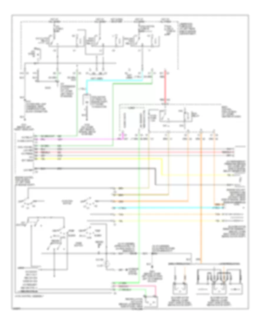
2.2L VIN F
2.2L VIN F, Manual A/C Wiring Diagram for Saturn Ion 3 2006
List of elements for 2.2L VIN F, Manual A/C Wiring Diagram for Saturn Ion 3 2006:
- (in i/p harness, 6.5 cm from blower motor breakout) s260
- (in i/p harness, approximately 20 cm from radio c1 breakout) s233
- (not used)
- +5v
- A/c clutch relay
- A/c compressor clutch (at lower left front of engine)
- A/c diode
- A/c fuse 5 10a
- A/c ind
- A/c press
- A/c refrigerant pressure sensor (on lower left side of engine, below generator)
- A/c relay
- A/c request
- A/c sig sw
- A/c switch
- A10
- Aa1
- Aa2
- Aa3
- Aa4
- B11
- Bi-lvl
- Blend
- Blower motor (behind lower right side of dash, behind glove compt)
- Blower motor resistor assembly (behind lower right side of dash, behind glove compt)
- Body control module (bcm) (at lower center of dash)
- Class 2 data
- Cool fan rel
- Cooling fan (at front of engine compt, attached to radiator)
- Cooling fan fuse 45 30a
- Cooling fan relay
- Def
- Early production
- Ect sens
- Engine control module (ecm) (at left side of engine compt)
- Engine coolant temperature (ect) sensor (on right rear side of engine, near exhaust manifold)
- F10
- G101 (behind left front headlamp)
- G105 (on lower left rear of engine, above starter)
- G203 (behind lower left side of dash, left of steering column)
- Hot at all times
- Hot in run or start
- Htr
- Hvac control assembly
- Hvac fan switch
- Hvac fuse 7.5a
- Ign 3 volt
- Illum
- Interior lights system
- Late production
- Logic
- Low ref
- Mode sw sig
- Mode switch
- Nca
- Off
- Rec dr ctrl a
- Rec dr ctrl b
- Rec sw sig
- Recirc ind
- Recirc switch
- Recirculation actuator (behind lower right side of dash, near "a" pillar)
- Red
- Run (ign 3) fuse 48 30a
- Run relay
- Run relay ctrl
- Run/ crank relay
- S101 (in forward lamp harness, near underhood fuse block connector)
- Tan
- Underhood fuse block (at left rear side of engine compartment)
- Vent
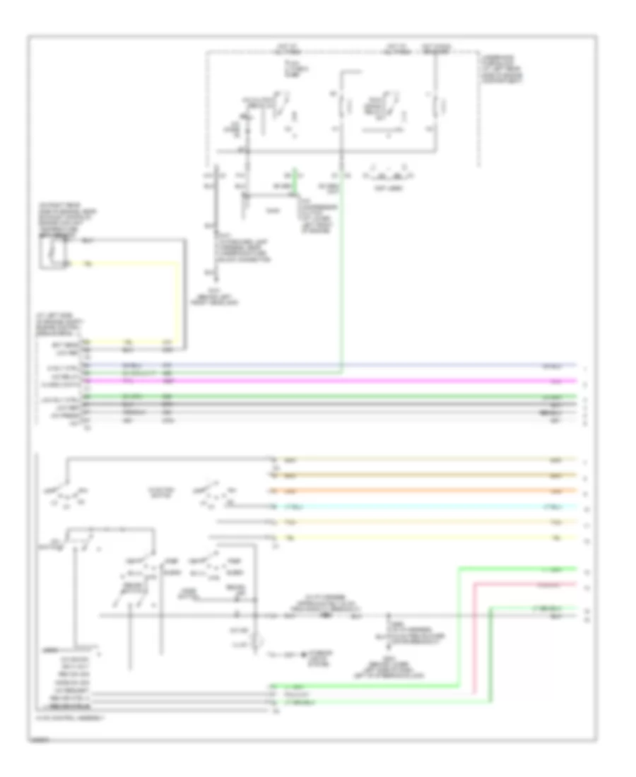
2.4L VIN B
2.4L VIN B, Manual A/C Wiring Diagram (1 of 2) for Saturn Ion 3 2006
List of elements for 2.4L VIN B, Manual A/C Wiring Diagram (1 of 2) for Saturn Ion 3 2006:
- (at left side of engine compt) engine control module (ecm)
- (in i/p harness, approximately 20 cm from radio c1 breakout) s233
- (not used)
- (on right rear side of engine, near exhaust manifold) engine coolant temperature (ect) sensor
- +5v
- A/c clutch relay 24
- A/c compressor clutch (at lower left front of engine)
- A/c diode
- A/c fuse 5 10a
- A/c ind
- A/c press
- A/c relay
- A/c request
- A/c sig sw
- A/c switch
- A10
- Bi-lvl
- Blend
- Class 2 data
- Def
- Ect sens
- F10
- G101 (behind left front headlamp)
- G203 (behind lower left side of dash, left of steering column)
- Hi rly ctrl
- Hot at all times
- Hot in run or start
- Htr
- Hvac control assembly
- Hvac fan switch
- Ign 3 volt
- Illum
- Interior lights system
- Logic
- Low ref
- Low rly ctrl
- Mode sw sig
- Mode switch
- Motor breakout)
- Off
- Rec dr ctrl a
- Rec dr ctrl b
- Rec sw sig
- Recirc ind
- Recirc switch
- Run/ crank relay
- S101 (in forward lamp harness, near underhood fuse block connector)
- Tan
- Underhood fuse block (at left rear side of engine compartment)
- Vent
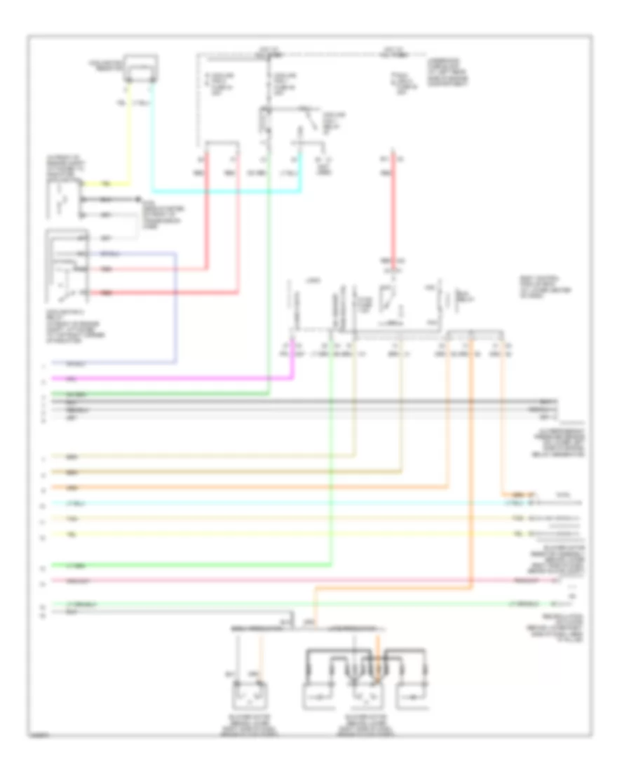
2.4L VIN B, Manual A/C Wiring Diagram (2 of 2) for Saturn Ion 3 2006
List of elements for 2.4L VIN B, Manual A/C Wiring Diagram (2 of 2) for Saturn Ion 3 2006:
- (in front of engine compt, attached to radiator) cooling fan
- (not used)
- A/c refrigerant pressure sensor (on lower left side of engine, below generator)
- A/c request
- Aa1
- Aa2
- Aa3
- Aa4
- B11
- Blower motor (behind lower right side of dash, behind glove compt)
- Blower motor resistor assembly (behind lower right side of dash, behind glove compt)
- Body control module (bcm) (at lower center of dash)
- Class 2 data
- Cooling fan 1 fuse 45 30a
- Cooling fan 1 relay
- Cooling fan 2 fuse 44 30a
- Cooling fan 2 relay (in front of engine compt, attached to top right corner of radiator)
- Cooling fan resistor
- E1 c1
- Early production
- G105 (near starter, on front of transmission case)
- Hot at all times
- Hvac fuse 7.5a
- Late production
- Logic
- Nca
- Recirculation actuator (behind lower right side of dash, near "a" pillar)
- Red
- Run (ign 3) fuse 48 30a
- Run relay
- Run relay ctrl
- Tan
- Underhood fuse block (at left rear side of engine compartment)