AUTOMOTIVE ELECTRICIANS PORTAL

AIR CONDITIONING – Saturn L100 2002 – SYSTEM WIRING DIAGRAMS

AIR CONDITIONING

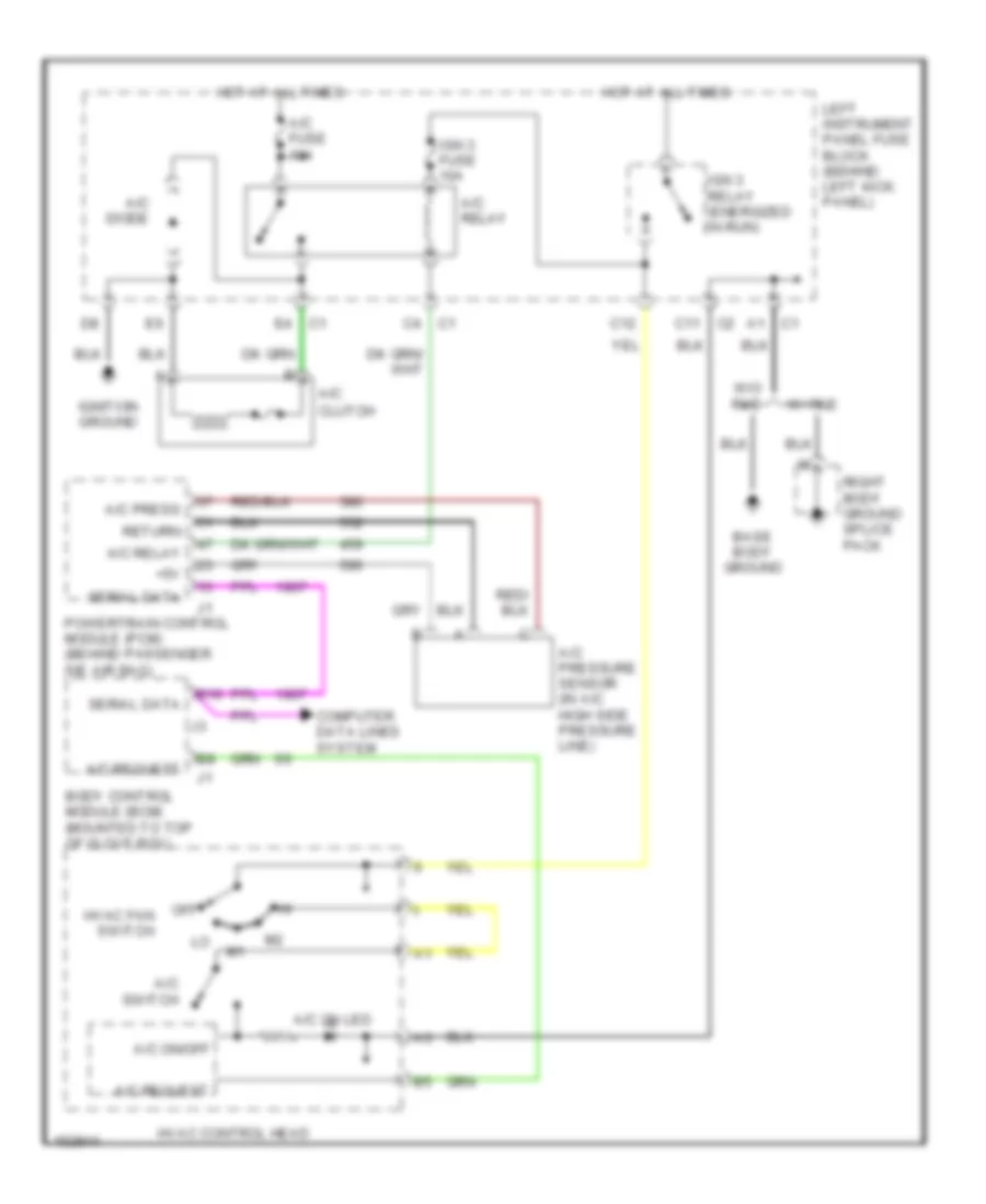
Compressor Wiring Diagram for Saturn L100 2002

Compressor Wiring Diagram for Saturn L100 2002 https://portal-diagnostov.com/license.html
https://portal-diagnostov.com/license.html Automotive Electricians Portal FZCO Automotive Electricians Portal FZCO
Get access to all wiring diagrams of the carDownload PDF file

List of elements for Compressor Wiring Diagram for Saturn L100 2002:

  • +5v
  • A/c
  • A/c diode
  • A/c fuse 10a
  • A/c on led
  • A/c on/off
  • A/c press
  • A/c pressure sensor (in a/c high side pressure line)
  • A/c relay
  • A/c request
  • A/c switch
  • B10
  • Base body ground
  • Body control module (bcm) (mounted to top of glove box)
  • C11
  • C12
  • Clutch
  • Computer data lines system
  • Hot at all times
  • Hvac control head
  • Hvac fan switch
  • Ign 3 fuse 10a
  • Ign 3 relay (energized in run)
  • Ignition ground
  • Left instrument panel fuse block (behind left kick panel)
  • Off
  • Powertrain control module (pcm) (behind passenger sie air bag)
  • Return
  • Right body ground splice pack
  • Serial data
  • W/ rke
  • W/o rke

Manual A/C Wiring Diagram (1 of 2) for Saturn L100 2002

Manual AC Wiring Diagram (1 of 2) for Saturn L100 2002 https://portal-diagnostov.com/license.html
https://portal-diagnostov.com/license.html Automotive Electricians Portal FZCO Automotive Electricians Portal FZCO
Get access to all wiring diagrams of the carDownload PDF file

List of elements for Manual A/C Wiring Diagram (1 of 2) for Saturn L100 2002:

  • (behind passenger side air bag) powertrain control module (pcm)
  • (in a/c high side pressure line) a/c pressure sensor
  • +5v
  • A/c clutch
  • A/c diode
  • A/c fuse 10a
  • A/c on led
  • A/c on/off input
  • A/c press sens
  • A/c relay
  • A/c relay control
  • A/c request input
  • A/c request output
  • A/c switch
  • A1 c1
  • B10
  • Base body ground
  • Blower motor (on hvac assembly)
  • Blower motor resistors (right side of hvac module)
  • Body control module (bcm) (mounted to top of glove box)
  • C11 c2
  • C12
  • Center console ground
  • Computer data lines system
  • Def
  • Def mode input
  • Defogger system
  • Dim illumination
  • Fan 1 ctrl
  • Fan 2 ctrl
  • Fresh output
  • Gnd
  • Grd
  • Hot at all times
  • Hot in run
  • Hvac control head
  • Hvac fan switch
  • Hvac in-line
  • Ign
  • Ign 3 fuse 10a
  • Ign 3 relay (energized in run)
  • Ignition ground
  • Interior lights system
  • Left instrument panel fuse block (lipfb) (behind left kick panel)
  • Mode door motor (on hvac module)
  • Mode input
  • Off
  • Pnk
  • Rear defogger switch
  • Recirc door motor (on hvac assembly)
  • Recirc on indicator
  • Recirc on input
  • Recirc output
  • Return
  • Right body ground splice pack
  • Serial data
  • Tan
  • Underhood fuse block
  • Vent
  • W/ rke
  • W/o rke

Manual A/C Wiring Diagram (2 of 2) for Saturn L100 2002

Manual AC Wiring Diagram (2 of 2) for Saturn L100 2002 https://portal-diagnostov.com/license.html
https://portal-diagnostov.com/license.html Automotive Electricians Portal FZCO Automotive Electricians Portal FZCO
Get access to all wiring diagrams of the carDownload PDF file

List of elements for Manual A/C Wiring Diagram (2 of 2) for Saturn L100 2002:

  • A12
  • Controls ign 1 fuse 10a
  • Cool fan 1 fuse 30a
  • Cool fan 2 fuse 30a
  • Cooling fan control module (near battery)
  • Engine cooling fan 1 (puller) (behind radiator)
  • Engine cooling fan 2 (pusher) (on front of a/c condenser)
  • F12
  • Hot at all times
  • Hot in run or start
  • Left forward lamp ground
  • Left forward lamp splice pack
  • Nca
  • Pnk
  • Red
  • Relay energized in high fan speed
  • Relay energized in low & high fan speed
  • Relay energized in low fan speed
  • Relay energized in medium fan speed
  • Underhood fuse block (uhfb) (left side of engine compt)