CRUISE CONTROL
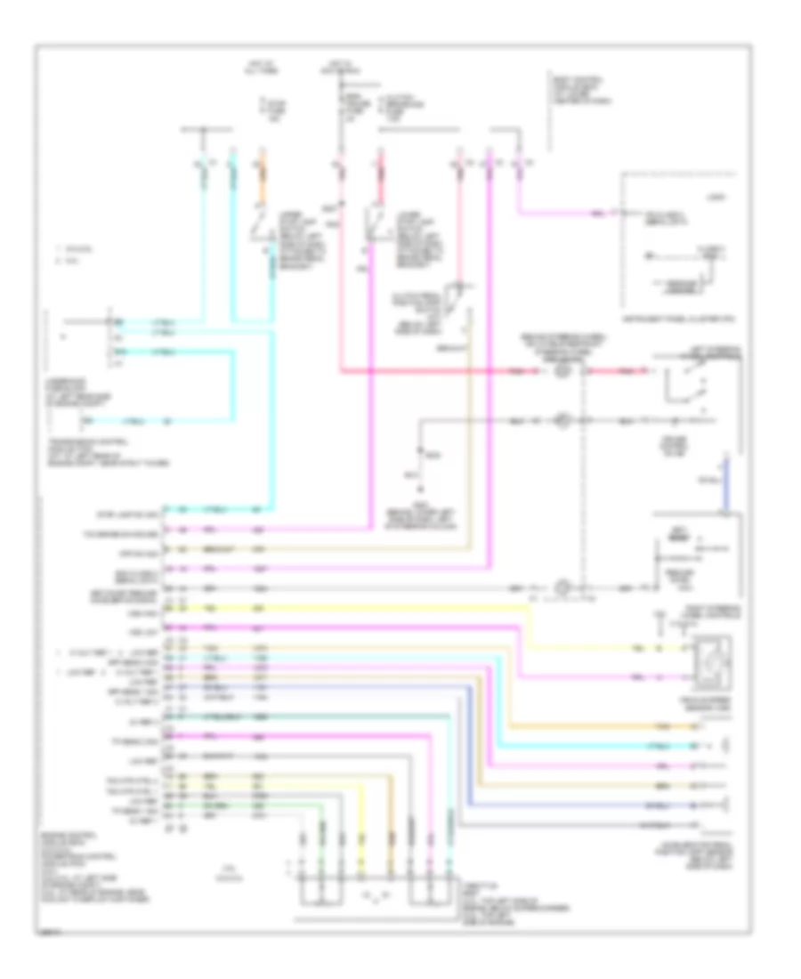
Cruise Control Wiring Diagram for Saturn Ion Red Line 2007
List of elements for Cruise Control Wiring Diagram for Saturn Ion Red Line 2007:
- (behind steering wheel) inflatable restraint steering wheel module coil
- 2.0l
- 2.0l/2.2l
- 2.2l/2.4l
- 2.4l
- 5 volt ref 1
- 5 volt ref 2
- 5v ref 1
- 5v ref 2
- Accelerator pedal position (app) sensor (below left side of dash)
- All times
- App sens 1 sig
- App sens 2 sig
- Body control module (bcm) (at lower center of dash)
- Class 2 ecm
- Clutch pedal position (cpp) switch (m/t) (below left side of dash)
- Clutch/ brake/aos fuse 7.5a
- Cpp sw sig
- Cruise control on ind
- E10
- Ecm class 2 serial data
- Engine control module (ecm) (2.2l/2.4l) powertrain control module (pcm) (2.0l) (2.2l/2.4l: at left side of engine compt) (2.0l: at rear of engine, near coolant overflow container)
- Eps/ cruise fuse 2a
- G203 (behind lower left side of dash, left of steering column)
- Hot at
- Hot in acc or run
- Instrument panel cluster (ipc)
- Ipc class 2 serial data
- Left steering wheel controls
- Logic
- Low ref
- Lower stop lamp switch (below left side of dash, attached to brake pedal bracket)
- Message center
- Pnk
- Resume/ accel
- Right steering wheel controls
- S227
- S233
- Set/ coast
- Set/coast resume/ accelerate signal
- Stop fuse 15a
- Stop lamp sw sig
- Tac mtr ctrl 1
- Tac mtr ctrl 2
- Tan
- Tcc brake sw/cruise
- Throttle body (2.0l: top left side of engine, below supercharger) (2.2l: top left side of engine)
- Tp sens 1 sig
- Tp sens 2 sig
- Transmission control module (tcm) (a/t: at left rear of engine compt, near strut tower)
- Underhood fuse block (at left rear side of engine compt)
- Upper stop lamp switch (below left side of dash, attached to brake pedal bracket)
- Vehicle speed sensor (vss)
- Vss high
- Vss low
 English