AIR CONDITIONING
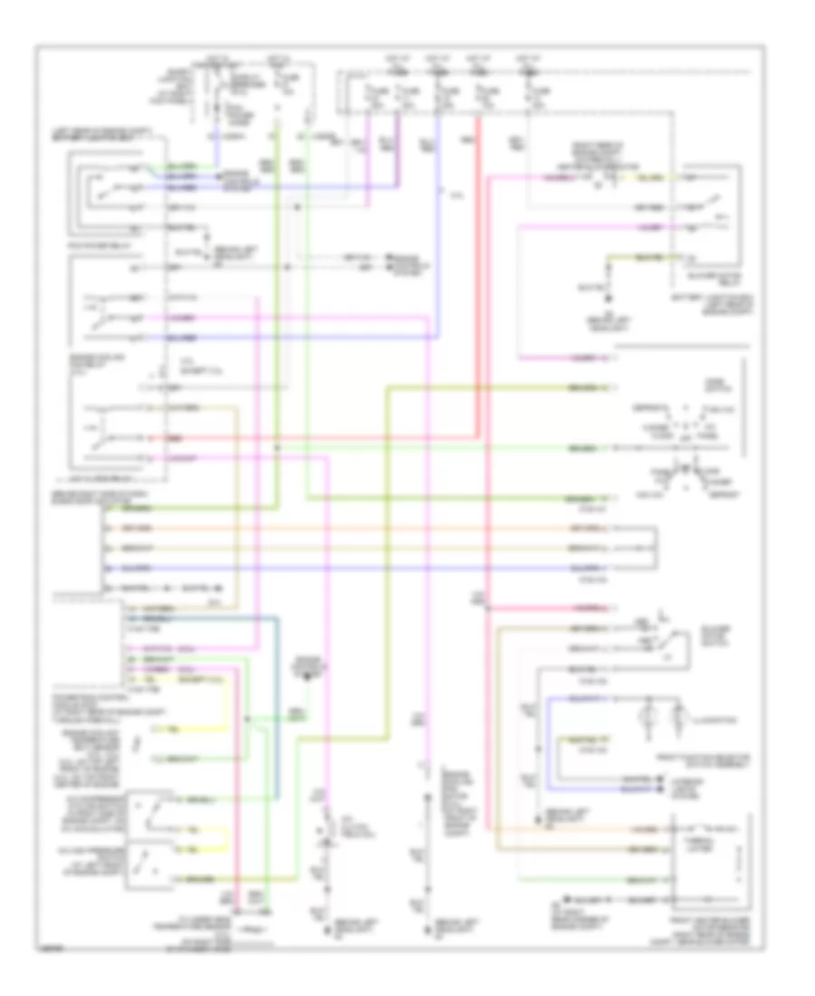
Manual A/C Wiring Diagram for Mazda B3000 Dual Sport 2007
List of elements for Manual A/C Wiring Diagram for Mazda B3000 Dual Sport 2007:
- (2.3l)
- (behind left headlight) g4
- (behind right side of dash) blend door actuator
- (except 2.3l)
- (left rear of engine compt) battery junction box
- (right rear of engine compt, on firewall) heater blower motor
- 0140-175b
- 0140-175e
- 0740-101
- 0740-102
- 0740-103
- 0740-104
- 2.3l
- A/c
- A/c clutch field coil
- A/c clutch relay
- A/c compressor cycling switch (in right side of engine compt, on a/c accumulator)
- A/c high pressure switch (at left front of engine compt)
- Battery junction box (left rear of engine compt)
- Blower motor relay
- Blower motor switch
- Circuit breaker ptc
- Cylinder head temperature sensor (2.3l) (on right side of cylinder head)
- Defrost
- Engine controls system
- Engine coolant temperature (ect) sensor (3.0l, 4.0l) (3.0l: on top left front of engine) (4.0l: on top front center of engine)
- Engine cooling fan motor (2.3l) (at right front of engine compt)
- Engine cooling fan relay (2.3l)
- Except 2.3l
- Floor
- Flr/def
- Front function selector switch assembly
- Front heater blower motor resistor (right rear of engine compt, near blower motor)
- Fuse 10a
- Fuse 20a
- Fuse 30a
- G13
- G4 (behind left headlight)
- G5 (at right rear corner of engine compt)
- Hot at all times
- Hot in on or start
- Hot in run
- Illumination
- Interior lights system
- J-2280a
- J-2280b
- Max a/c
- Med hi
- Med lo
- Mode switch
- Off
- Panel
- Pcm power diode
- Pcm power relay
- Powertrain control module (pcm) (at right rear of engine compt, through firewall)
- Red
- Smart junction box (at right kick panel)
- Thermal limiter
 English