AIR CONDITIONING
3.0L
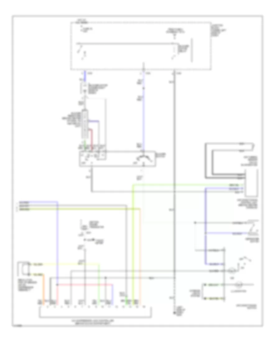
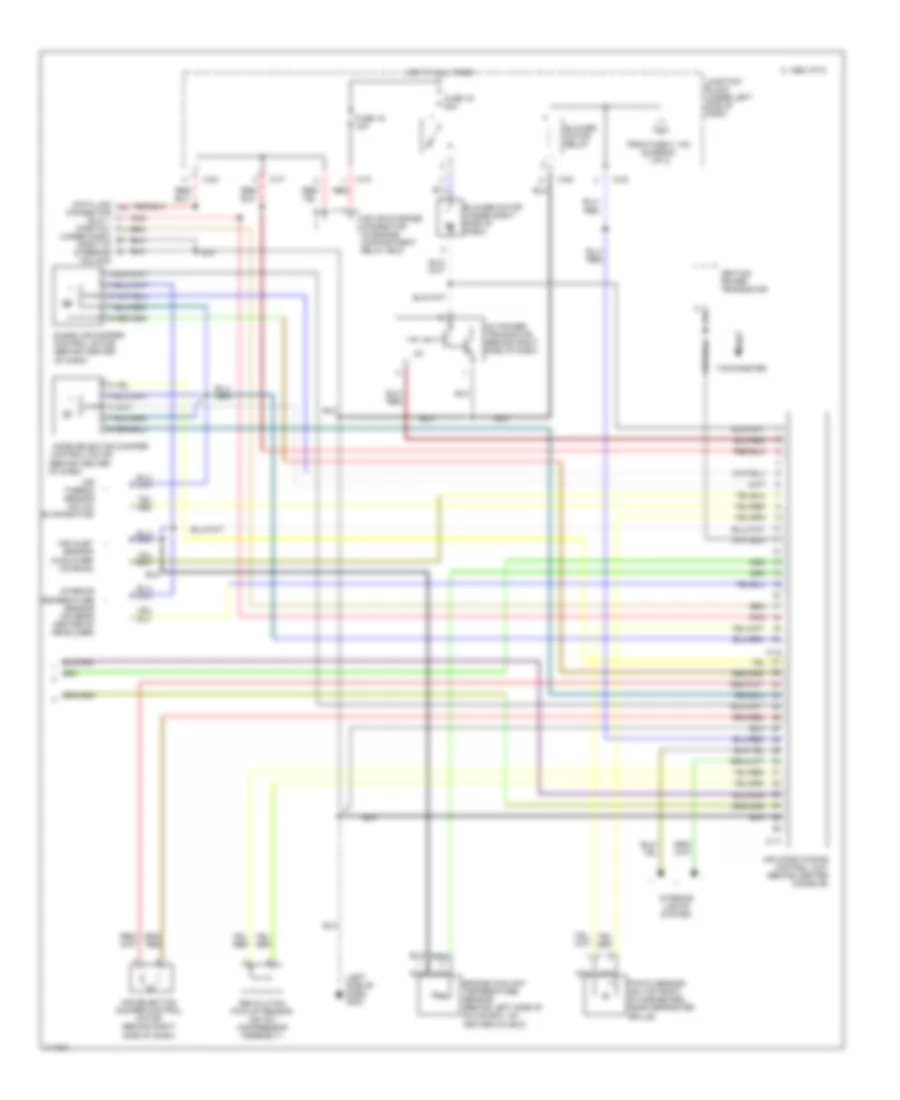
3.0L DOHC, Manual A/C Wiring Diagram (1 of 2) for Mitsubishi 3000GT VR-4 1999

List of elements for 3.0L DOHC, Manual A/C Wiring Diagram (1 of 2) for Mitsubishi 3000GT VR-4 1999:
- (left front fender) g100
- (open above
- (open below
- (right front fender) g101
- (right side of firewall) g123
- 28 psi)
- 455 psi)
- A/c relay box (dedicated fuses) (on left side of engine compartment, in front of shock tower)
- A/c relay box (on left side of engine compartment, in front of shock tower)
- A/t only
- All times
- C-46
- C-52
- C-53
- C-54
- C-69
- C-71
- C-83
- Condenser fan motor
- Condenser fan motor relay (hi)
- Condenser fan motor relay (lo)
- Dual pressure switch (left side of engine compartment)
- Elc-4 a/t control module (behind center console)
- Engine compartment relay box (on right side of engine compartment near shock tower)
- Engine compartment relay box (on right side of engine compartment, near shock tower)
- Engine control module (behind center console)
- Engine coolant temperature sensor (on right rear of engine)
- Fuse 11 15a
- Fuse 3 10a
- Fuse 8 20a
- Fuse 9 10a
- Fusible link 5 40a
- Hot at
- Hot in on
- Hot in on or start
- Junction block (under left side of dash)
- Magnetic clutch (on compressor)
- Magnetic clutch relay
- Radiator fan motor (on right front of engine compartment)
- Radiator fan relay (hi)
- Radiator fan relay (lo)
- Resistor (part of radiator fan assembly)
- Solid state
- Speed sensor (right side of transaxle)
- To blower relay (diagram 2 of 2)
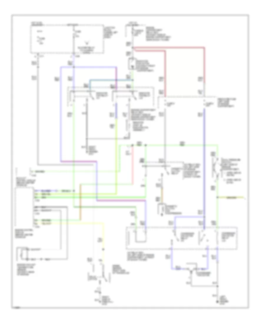
3.0L DOHC, Manual A/C Wiring Diagram (2 of 2) for Mitsubishi 3000GT VR-4 1999
List of elements for 3.0L DOHC, Manual A/C Wiring Diagram (2 of 2) for Mitsubishi 3000GT VR-4 1999:
- (left side of dash) g202
- A/c compressor lock controller (behind glove compartment)
- Air conditioning control unit (behind center console)
- Air conditioning switch
- Air thermo sensor (on a/c evaporator)
- B-21
- Blower motor (under right side of dash)
- Blower motor relay
- Blower resistors (behind center of dash, on heater-a/c unit)
- Blower switch
- C-82
- C-83
- Defroster switch
- From fuse 3 (diagram 1 of 2)
- Fuse 16 30a
- Hot at all times
- Ignition power transistor
- Illumination
- Ind
- Interior lights system
- Junction block (under left side of dash)
- Nca
- Off
- Red
- Revolution pick up sensor (on a/c compressor assembly)
- Rpm out
- Tacho- meter
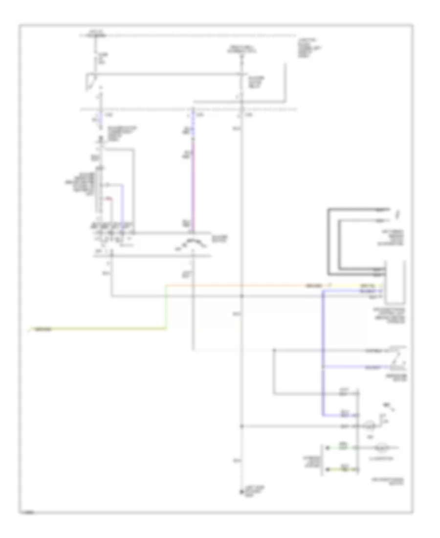
3.0L SOHC, Manual A/C Wiring Diagram (1 of 2) for Mitsubishi 3000GT VR-4 1999
List of elements for 3.0L SOHC, Manual A/C Wiring Diagram (1 of 2) for Mitsubishi 3000GT VR-4 1999:
- (left front fender) g100
- (open above 28 psi)
- (open above 455 psi)
- (right front fender) g101
- (right side of firewall) g123
- (to diagram 2 of 2)
- A/c relay box (on left side of engine compartment, in front of shock tower)
- A/t only
- All times
- Blower relay
- C-46
- C-52
- C-53
- C-54
- C-69
- C-71
- Condenser fan motor
- Condensor fan motor relay (hi)
- Condensor fan motor relay (lo)
- Dedicated fuse (left side of engine compartment)
- Dual pressure switch (left side of engine compartment)
- Elc-4 a/t control module (behind center console)
- Engine compartment relay box (on right side of engine compartment near shock tower)
- Engine compartment relay box (on right side of engine compartment, near shock tower)
- Engine control module (behind center console)
- Engine coolant temperature sensor (on right rear of engine)
- Fuse 10a
- Fuse 15a
- Fuse 8 20a
- Fuse 9 10a
- Fusible link 5 40a
- Hot at
- Hot in on
- Hot in on or start
- Junction block (under left side of dash)
- Magnetic clutch (on compressor)
- Magnetic clutch relay
- Radiator fan motor (on right front of engine compartment)
- Radiator fan relay (hi)
- Radiator fan relay (lo)
- Resistor (part of radiator fan assembly)
- Solid state
- Speed sensor (right side of transaxle)
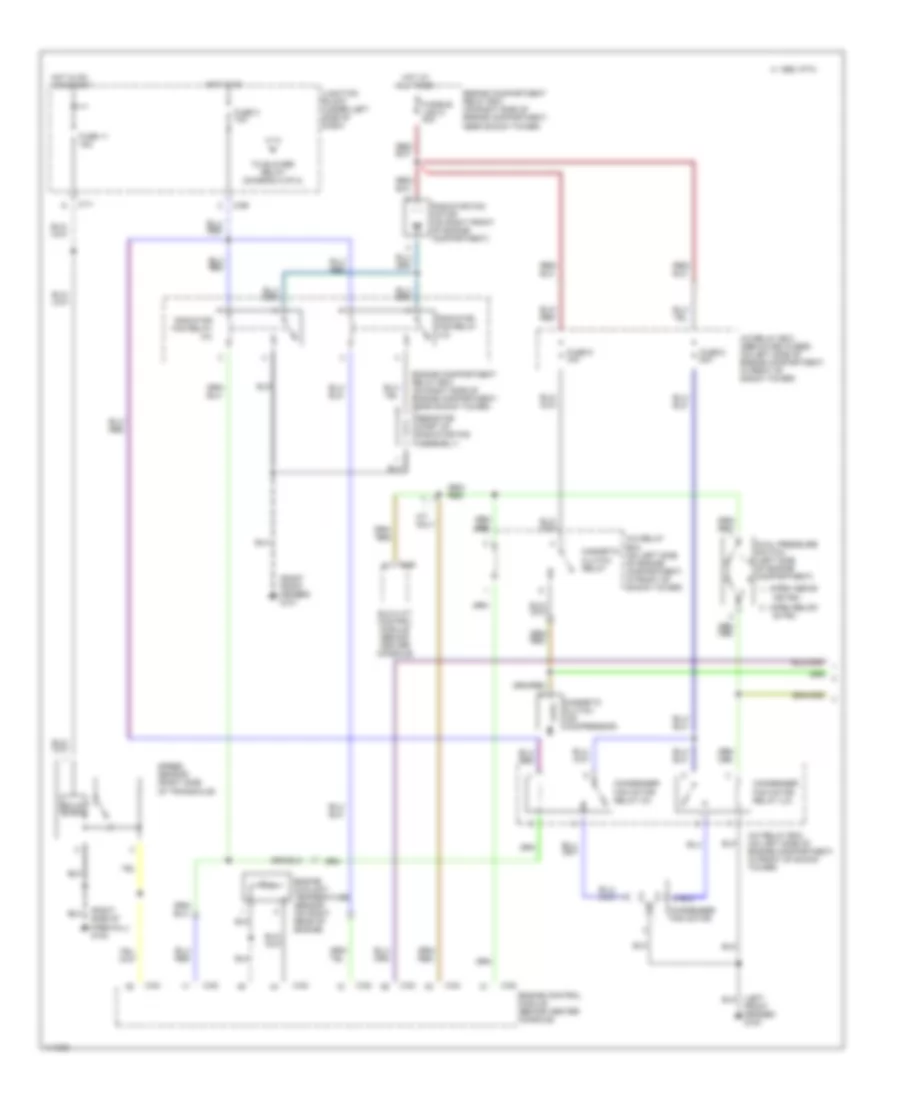
3.0L SOHC, Manual A/C Wiring Diagram (2 of 2) for Mitsubishi 3000GT VR-4 1999
List of elements for 3.0L SOHC, Manual A/C Wiring Diagram (2 of 2) for Mitsubishi 3000GT VR-4 1999:
- (left side of dash) g202
- Air conditioning control unit (behind center console)
- Air conditioning switch
- Air thermo sensor (on a/c evaporator)
- Blower motor (under right side of dash)
- Blower motor relay
- Blower resistors (behind center of dash, on heater-a/c unit)
- Blower switch
- C-82
- C-83
- Defroster switch
- From fuse 3, (diagram 1 of 2)
- Fuse 30a
- Hot at all times
- Illumination
- Ind
- Interior lights system
- Junction block (under left side of dash)
- Nca
- Off
- Red
Automatic A/C Wiring Diagram (1 of 2) for Mitsubishi 3000GT VR-4 1999
List of elements for Automatic A/C Wiring Diagram (1 of 2) for Mitsubishi 3000GT VR-4 1999:
- (left front fender) g100
- (open above
- (open below
- (right front fender) g101
- (right side of firewall) g123
- 28 psi)
- 455 psi)
- A/c relay box (dedicated fuses) (on left side of engine compartment, in front of shock tower)
- A/c relay box (on left side of engine compartment, in front of shock tower)
- A/t only
- All times
- C 1995 vftc
- C-46
- C-52
- C-53
- C-54
- C-69
- C-71
- Condenser fan motor
- Condenser fan motor relay (hi)
- Condenser fan motor relay (lo)
- Dual pressure switch (left side of engine compartment)
- Elc-4 a/t control module (behind center console)
- Engine compartment relay box (on right side of engine compartment, near shock tower)
- Engine control module (behind center console)
- Engine coolant temperature sensor (on right rear of engine)
- Fuse 11 15a
- Fuse 3 10a
- Fuse 8 20a
- Fuse 9 10a
- Fusible link 5 40a
- Hot at
- Hot in on
- Hot in on or start
- Junction block (under left side of dash)
- Magnetic clutch (on compressor)
- Magnetic clutch relay
- Radiator fan motor (on right front of engine compartment)
- Radiator fan relay (hi)
- Radiator fan relay (lo)
- Resistor (part of radiator fan assembly)
- Solid state
- Speed sensor (right side of transaxle)
- To blower relay (diagram 2 of 2)
Automatic A/C Wiring Diagram (2 of 2) for Mitsubishi 3000GT VR-4 1999
List of elements for Automatic A/C Wiring Diagram (2 of 2) for Mitsubishi 3000GT VR-4 1999:
- (behind center of dash)
- (left side of dash) g202
- (under dash, right of steering column)
- A/c power transistor (behind right side of dash)
- Air conditioning control unit (behind center console)
- Air inlet sensor (in blower housing)
- Air selection damper control motor (behind right side of dash)
- Air thermo sensor (on a/c evaporator)
- Blend air damper control motor (behind center of dash)
- Blower motor (under right side of dash)
- Blower motor relay
- C 1995 vftc
- C-16
- C-17
- C-70
- C-77
- C-82
- C-83
- Connector (dlc) 1 (partial)
- Control motor
- Data link
- Engine coolant temperature sensor (behind left side of glove box, on heater-a/c box)
- From fuse 3, 10a (diagram 1 of 2)
- Fuse 16 30a
- Fuse 19 10a
- Hot at all times
- Ignition power transistor
- Interior lights system
- Interior temperature sensor (on rear center of headliner)
- Iod or storage connector (in engine compartment relay box)
- Junction block (under left side of dash)
- Mode selection damper
- Nca
- Photo sensor (on top right of dashboard, near defroster grille)
- Pnk
- Red
- Revolution pick-up sensor (on a/c compressor assembly)
- Tachometer