AIR CONDITIONING
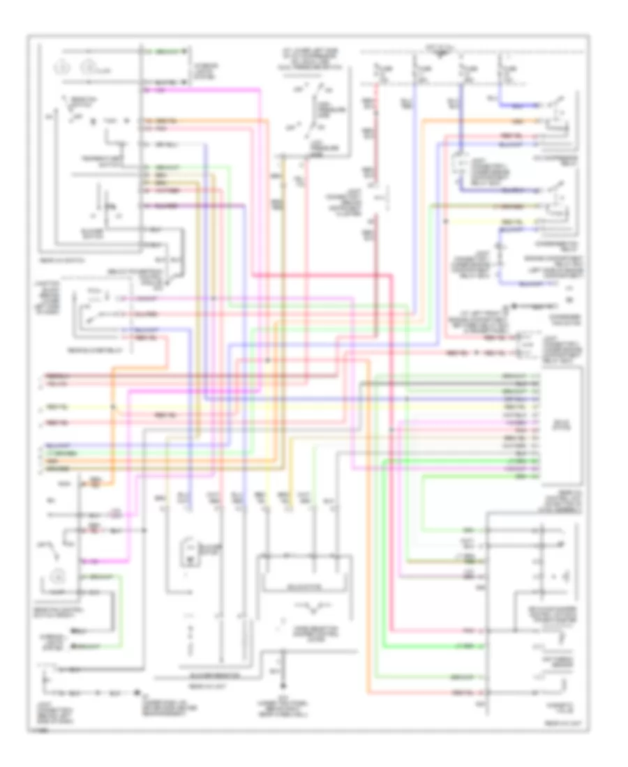
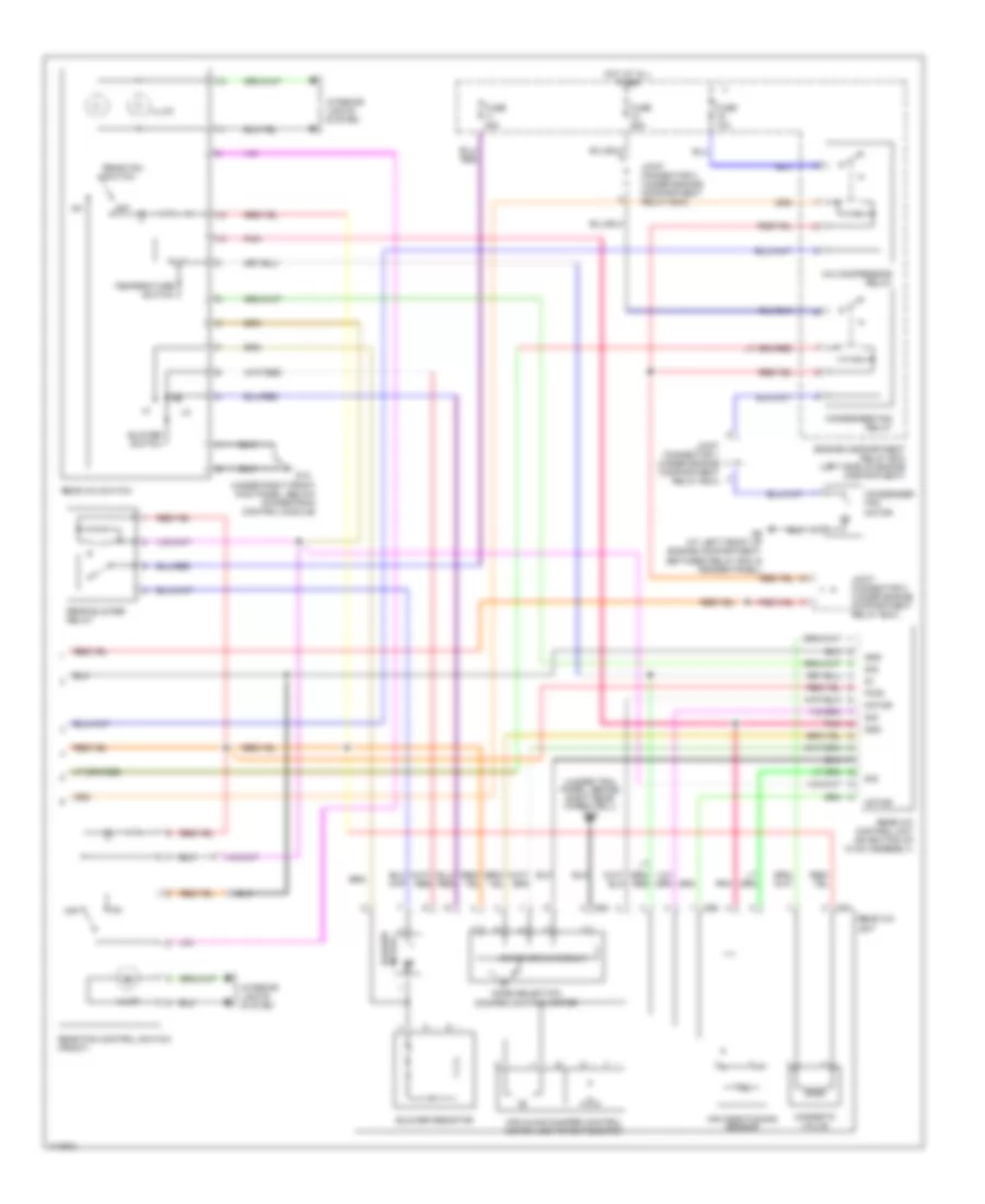
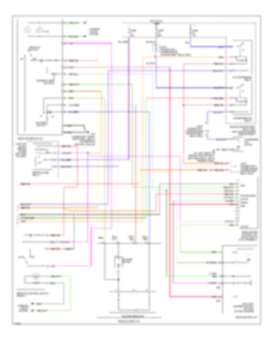
Automatic A/C Wiring Diagram, with Rear A/C (1 of 2) for Mitsubishi Montero XLS 2003

List of elements for Automatic A/C Wiring Diagram, with Rear A/C (1 of 2) for Mitsubishi Montero XLS 2003:
- A/c compressor
- A/c ecu (behind center of dash)
- Air conditioning sensor (on hvac assembly)
- Air mixing damper control motor & potentiometer
- Blower motor
- D08
- D132
- D134
- D208
- D209
- D210
- D220
- D23
- D24
- Data link connector (lower left side
- Defogger system
- Front blower relay
- Fuse 10a
- Fuse 15a
- Fuse 30a
- G7 (under dash, on driver side center reinforcement)
- G8 (under dash, on passenger side reinforcement)
- Heater blower controller unit (on hvac assembly)
- Heater water temperature sensor (on hvac assembly)
- Hot at all times
- Hot in acc
- Hot in on
- Interior lights system
- Joint connector 5 (behind left side of dash)
- Joint connector 6 (behind instrument cluster)
- Joint connector 8 (behind left side of dash)
- Junction block (behind lower left side of dash)
- Lock sensor
- Magnetic clutch
- Mode selection damper control motor & potentiometer
- Of dash, right of steering column)
- Outside air temperature sensor (at lower right front of a/c condenser)
- Outside/ inside air selection damper control motor
- Photo sensor (on top center of dash)
- Pnk
- Powertrain control module (behind lower right side of dash)
- Red
- Rv meter
- Solid state
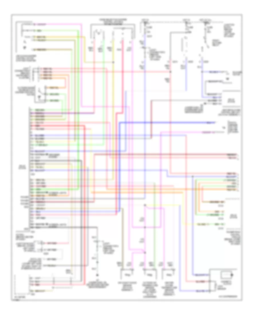
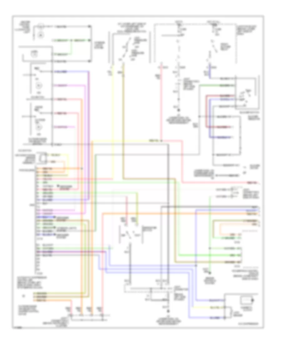
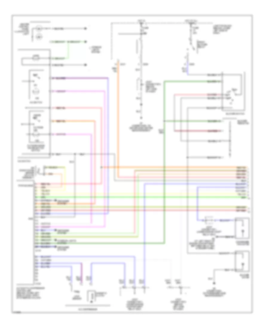
Automatic A/C Wiring Diagram, with Rear A/C (2 of 2) for Mitsubishi Montero XLS 2003
List of elements for Automatic A/C Wiring Diagram, with Rear A/C (2 of 2) for Mitsubishi Montero XLS 2003:
- (at lower left side of a/c compressor, on liquid line) dual pressure switch
- (below powertrain control module) g12
- A/c compressor relay
- Air mixing damper control motor & potentiometer
- Air thermo sensor
- Blower motor
- Blower resistor
- Blower switch
- Condenser fan motor
- Condenser fan relay
- Engine compartment relay box (left side of engine compartment)
- Fuse 10a
- Fuse 20a
- Fuse 25a
- G15 (under trim panel, behind right rear wheelwell)
- G24
- G26
- G6 (at left front of engine compartment, between relay box & fender panel)
- G7 (under dash, on driver side center reinforcement)
- High- pressure side
- Hot at all times
- Illum
- Interior lights system
- Joint connector 1 (under engine compartment relay box)
- Joint connector 2 (under engine compartment relay box)
- Joint connector 3 (under engine compartment relay box)
- Joint connector 7 (behind instrument cluster)
- Joint connector 8 (behind left side of dash)
- Junction block (behind lower left side of dash)
- Low- pressure side
- Magnetic valve
- Mode selection damper control motor
- Off
- Pnk
- Rear a/c control unit (on bottom of hvac assembly)
- Rear a/c switch
- Rear a/c unit
- Rear blower relay
- Rear fan control switch (front)
- Rear fan switch
- Solid state
- Temperature switch
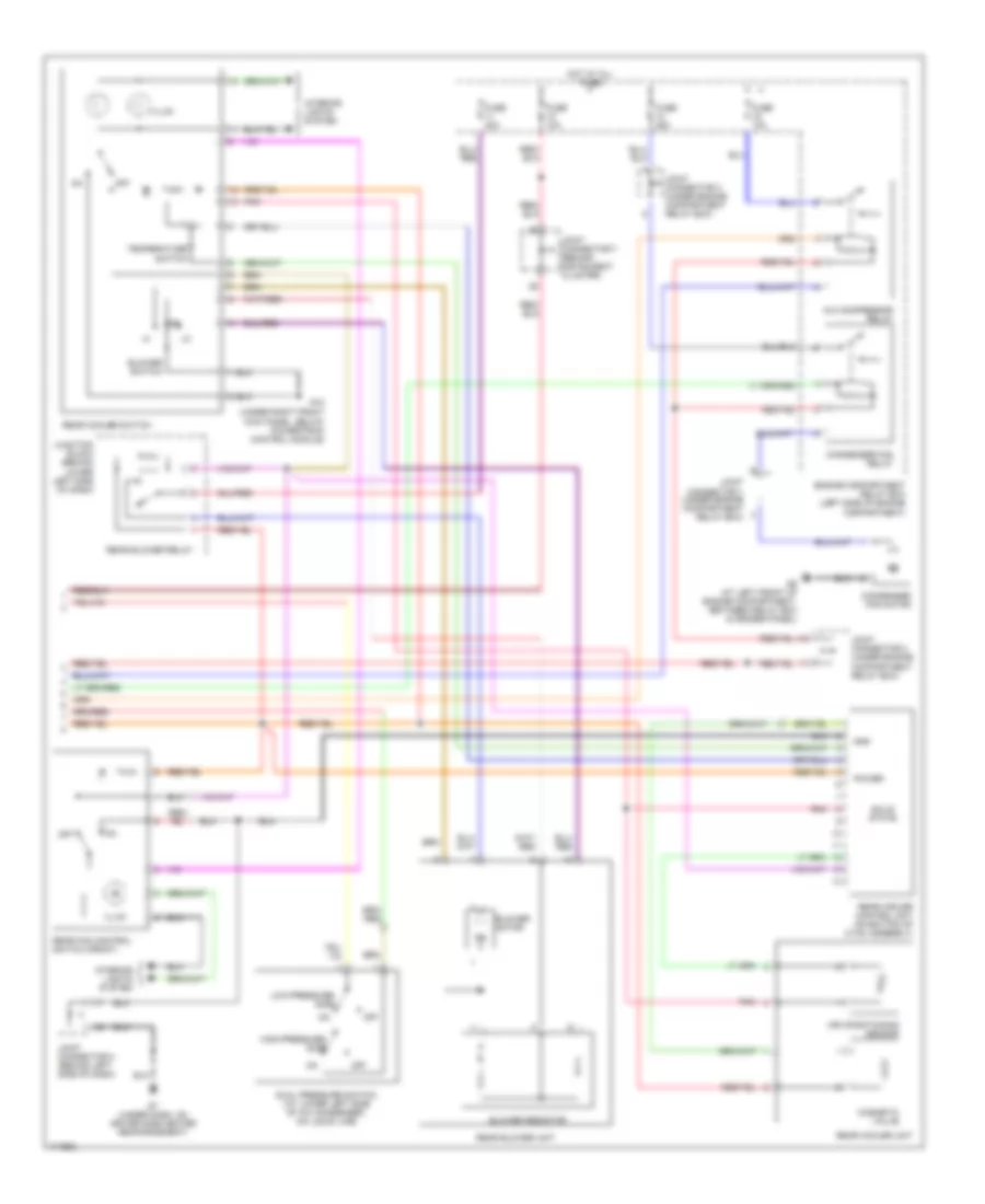
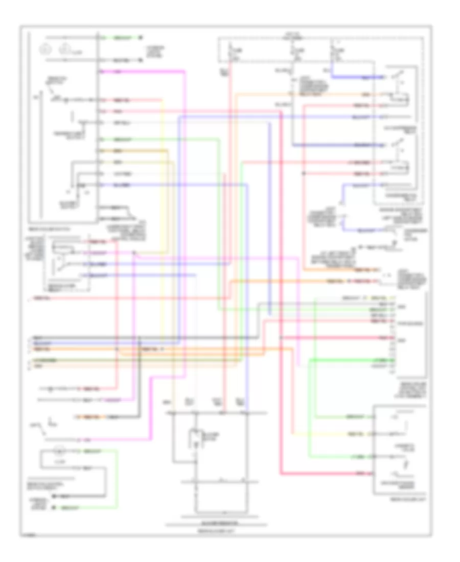
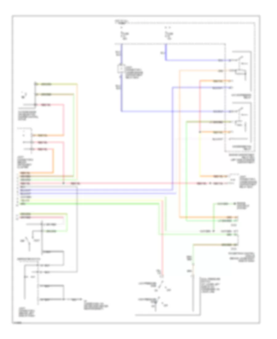
Automatic A/C Wiring Diagram, with Rear Cooler (1 of 2) for Mitsubishi Montero XLS 2003
List of elements for Automatic A/C Wiring Diagram, with Rear Cooler (1 of 2) for Mitsubishi Montero XLS 2003:
- A/c compressor
- A/c ecu (behind center of dash)
- Air conditioning sensor (on hvac assembly)
- Air mixing damper control motor & potentiometer
- Blower motor
- Connector (lower left side of dash, right of steering column)
- D08
- D132
- D134
- D208
- D209
- D210
- D220
- D23
- D24
- Data link
- Defogger system
- Front blower relay
- Fuse 10a
- Fuse 15a
- Fuse 30a
- G7 (under dash, on driver side center reinforcement)
- G8 (under dash, on passenger side reinforcement)
- Gnd
- Heater blower controller unit (on hvac assembly)
- Heater water temperature sensor (on hvac assembly)
- Hot at all times
- Hot in acc
- Hot in on
- Interior lights system
- Joint connector 5 (behind left side of dash)
- Joint connector 6 (behind instrument cluster)
- Joint connector 8 (behind left side of dash)
- Junction block (behind lower left side of dash)
- Lock sensor
- Magnetic clutch
- Mode selection damper control motor & potentiometer
- Outside air temperature sensor (at lower right front of a/c condenser)
- Outside/inside air selection damper control motor
- Photo sensor (on top center of dash)
- Pnk
- Power
- Powertrain control module (behind lower right side of dash)
- Red
- Rv meter
- Solid state
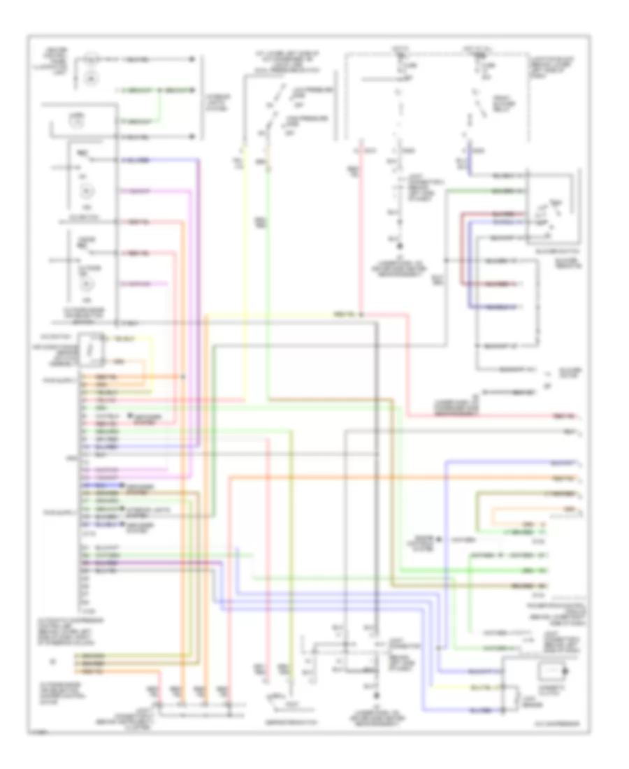
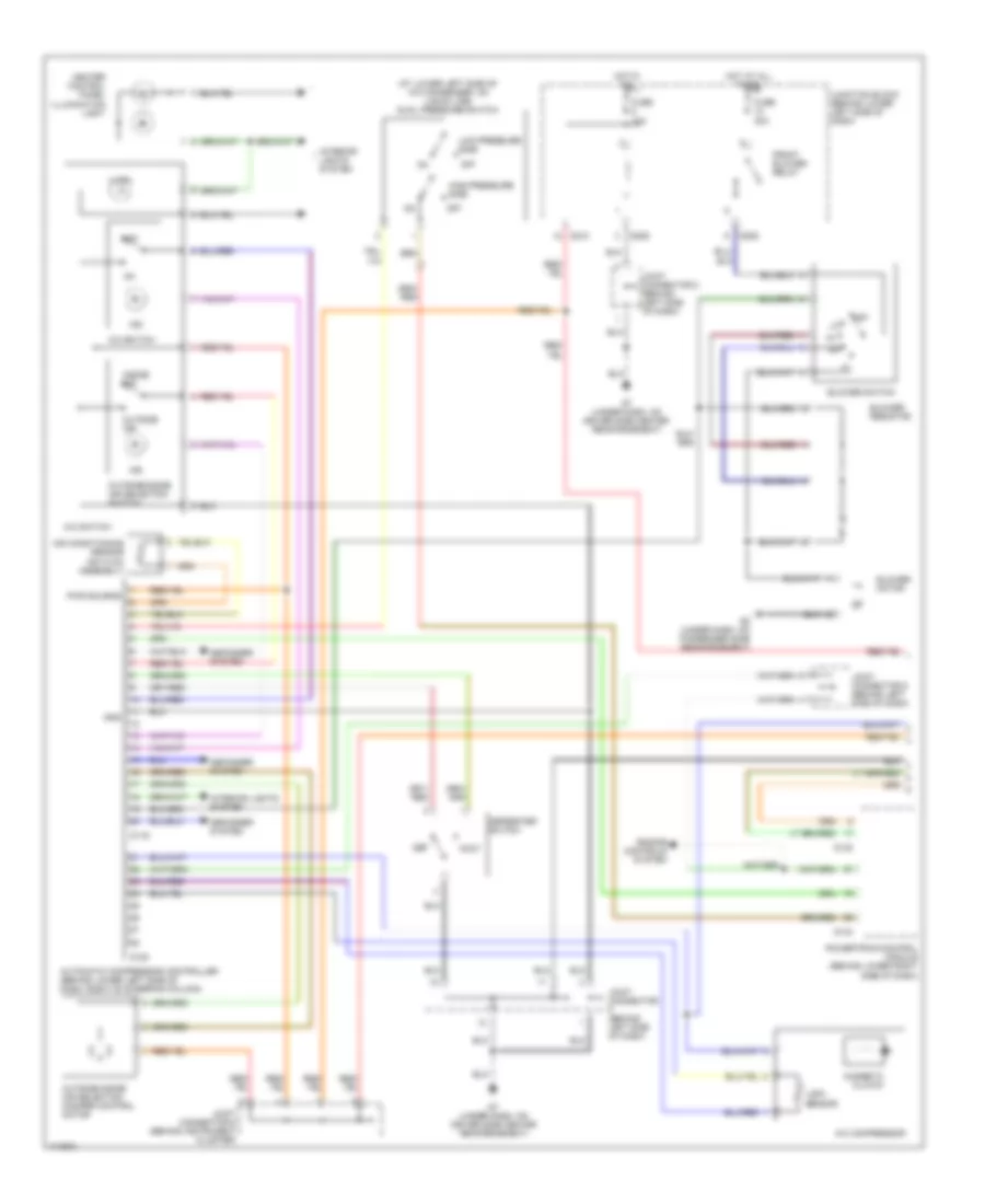
Automatic A/C Wiring Diagram, with Rear Cooler (2 of 2) for Mitsubishi Montero XLS 2003
List of elements for Automatic A/C Wiring Diagram, with Rear Cooler (2 of 2) for Mitsubishi Montero XLS 2003:
- (under right front kick panel, below powertrain control module)
- A/c compressor relay
- Air conditioning sensor
- Blower motor
- Blower resistor
- Blower switch
- Condenser fan motor
- Condenser fan relay
- Dual pressure switch (at lower left side of a/c condenser, on liquid line)
- Engine compartment relay box (left side of engine compartment)
- Fuse 10a
- Fuse 20a
- Fuse 25a
- G12
- G6 (at left front of engine compartment, between relay box & fender panel)
- G7 (under dash, on driver side center reinforcement)
- Gnd
- High-pressure side
- Hot at all times
- Illum
- Interior lights system
- Joint connector 1 (under engine compartment relay box)
- Joint connector 2 (under engine compartment relay box)
- Joint connector 3 (under engine compartment relay box)
- Joint connector 7 (behind instrument cluster)
- Joint connector 8 (behind left side of dash)
- Junction block (behind lower left side of dash)
- Low-pressure side
- Magnetic valve
- Off
- Pnk
- Power
- Rear blower relay
- Rear blower unit
- Rear cooler control unit (on bottom of hvac assembly)
- Rear cooler switch
- Rear cooler unit
- Rear fan control switch (front)
- Solid state
- Temperature switch
Manual A/C Wiring Diagram, Dual A/C Wiring Diagram with Rear A/C (1 of 2) for Mitsubishi Montero XLS 2003
List of elements for Manual A/C Wiring Diagram, Dual A/C Wiring Diagram with Rear A/C (1 of 2) for Mitsubishi Montero XLS 2003:
- (at lower left side of a/c condenser, on liquid line) dual pressure switch
- A/c compressor
- A/c switch
- Air conditioning sensor (on hvac assembly)
- Automatic compressor controller (behind lower left side of dash, right of steering column)
- Blower motor
- Blower resistor
- Blower switch
- D119
- D120
- D132
- D134
- D208
- D209
- D210
- Def
- Defogger system
- Defroster switch
- Engine controls system
- Foot
- Front blower relay
- Fuse 10a
- Fuse 30a
- G7 (under dash, on driver side center reinforcement)
- G7 (under dash, on driver side center reinforcement)
- G8 (under dash, on passenger side reinforcement)
- Gnd
- Heater control panel illumination light
- High-pressure side
- Hot at all times
- Hot in on
- Illum
- Ind
- Inside air
- Interior lights system
- Joint connector (behind left side of dash)
- Joint connector 5 (behind left side of dash)
- Joint connector 6 (behind instrument cluster)
- Joint connector 8 (behind left side of dash)
- Junction block (behind lower left side of dash)
- Lock sensor
- Low-pressure side
- Magnetic clutch
- Off
- Outside air
- Outside/inside air selection damper control motor
- Outside/inside air selection switch
- Powertrain control module (behind lower right side of dash)
Manual A/C Wiring Diagram, Dual A/C Wiring Diagram with Rear A/C (2 of 2) for Mitsubishi Montero XLS 2003
List of elements for Manual A/C Wiring Diagram, Dual A/C Wiring Diagram with Rear A/C (2 of 2) for Mitsubishi Montero XLS 2003:
- (under right front kick panel, below powertrain control module)
- (under trim panel, behind right rear wheelwell) g15
- A/c compressor relay
- Air conditioning sensor
- Air mixing damper control motor and potentiometer
- Blower motor
- Blower resistor
- Blower switch
- Condenser fan motor
- Condenser fan relay
- Engine compartment relay box (left side of engine compartment)
- Fuse 10a
- Fuse 20a
- Fuse 25a
- G12
- G22
- G24
- G26
- G6 (at left front of engine compartment, between relay box & fender panel)
- Gnd
- Hot at all times
- Illum
- Interior lights system
- Joint connector 1 (under engine compartment relay box)
- Joint connector 2 (under engine compartment relay box)
- Joint connector 3 (under engine compartment relay box)
- Magnetic valve
- Mode selection damper control motor
- Motor
- Motor drive circuit
- Off
- Pnk
- Pwr
- Rear a/c
- Rear a/c control unit (on bottom of hvac assembly)
- Rear a/c switch
- Rear blower relay
- Rear fan control switch (front)
- Rear fan switch
- Sig
- Temperature switch
- Unit
Manual A/C Wiring Diagram, Dual A/C Wiring Diagram with Rear Cooler (1 of 2) for Mitsubishi Montero XLS 2003
List of elements for Manual A/C Wiring Diagram, Dual A/C Wiring Diagram with Rear Cooler (1 of 2) for Mitsubishi Montero XLS 2003:
- (at lower left side of a/c condenser, on liquid line) dual pressure switch
- (behind left side of dash)
- (under dash, on passenger side reinforcement) g8
- A/c compressor
- A/c switch
- Air conditioning sensor (on hvac assembly)
- Automatic compressor controller (behind lower left side of dash, right of steering column)
- Blower motor
- Blower resistor
- Blower switch
- D119
- D120
- D132
- D134
- D208
- D209
- D210
- Def
- Defogger system
- Defroster switch
- Engine controls system
- Foot
- Front blower relay
- Fuse 10a
- Fuse 30a
- G7 (under dash, on driver side center reinforcement)
- Gnd
- Heater control panel illumination light
- High- pressure side
- Hot at all times
- Hot in on
- Illum
- Ind
- Inside air
- Interior lights system
- Joint connector
- Joint connector 5 (behind left side of dash)
- Joint connector 6 (behind instrument cluster)
- Joint connector 8 (behind left side of dash)
- Junction block (behind lower left side of dash)
- Lock sensor
- Low- pressure side
- Magnetic clutch
- Off
- Outside air
- Outside/inside air selection damper control motor
- Outside/inside air selection switch
- Powertrain control module (behind lower right side of dash)
- Pwr source
Manual A/C Wiring Diagram, Dual A/C Wiring Diagram with Rear Cooler (2 of 2) for Mitsubishi Montero XLS 2003
List of elements for Manual A/C Wiring Diagram, Dual A/C Wiring Diagram with Rear Cooler (2 of 2) for Mitsubishi Montero XLS 2003:
- A/c compressor relay
- Air conditioning sensor
- Blower motor
- Blower resistor
- Blower switch
- Condenser fan motor
- Condenser fan relay
- Engine compartment relay box (left side of engine compartment)
- Fuse 10a
- Fuse 20a
- Fuse 25a
- G12 (under right front kick panel, below powertrain control module)
- G6 (at left front of engine compartment, between relay box & fender panel)
- Gnd
- Hot at all times
- Illum
- Interior lights system
- Joint connector 1 (under engine compartment relay box)
- Joint connector 2 (under engine compartment relay box)
- Joint connector 3 (under engine compartment relay box)
- Junction block (behind lower left side of dash)
- Magnetic valve
- Off
- Pnk
- Pwr source
- Rear blower relay
- Rear blower unit
- Rear cooler control unit (on bottom of hvac assembly)
- Rear cooler switch
- Rear cooler unit
- Rear fan control switch (front)
- Rear fan switch
- Temperature switch
Manual A/C Wiring Diagram, Dual A/C Wiring Diagram with Rear Heater (1 of 2) for Mitsubishi Montero XLS 2003
List of elements for Manual A/C Wiring Diagram, Dual A/C Wiring Diagram with Rear Heater (1 of 2) for Mitsubishi Montero XLS 2003:
- (at lower left side of a/c condenser, on liquid line) dual pressure switch
- (behind left side of dash)
- A/c compressor
- A/c switch
- Air conditioning sensor (on hvac assembly)
- Automatic compressor controller (behind lower left side of dash, right of steering column)
- Blower motor
- Blower resistor
- Blower switch
- D119
- D120
- D132
- D134
- D208
- D209
- D210
- Def
- Defogger system
- Defroster switch
- Engine controls system
- Foot
- Front blower relay
- Fuse 10a
- Fuse 30a
- G7 (under dash, on driver side center reinforcement)
- G8 (under dash, on passenger side reinforcement)
- Gnd
- Heater control panel illumination light
- High-pressure side
- Hot at all times
- Hot in on
- Illum
- Ind
- Inside air
- Interior lights system
- Joint connector
- Joint connector 5 (behind left side of dash)
- Joint connector 6 (behind instrument cluster)
- Joint connector 8 (behind left side of dash)
- Junction block (behind lower left side of dash)
- Lock sensor
- Low-pressure side
- Magnetic clutch
- Off
- Outside air
- Outside/inside air selection damper control motor
- Outside/inside air selection switch
- Powertrain control module (behind lower right side of dash)
- Pwr source
Manual A/C Wiring Diagram, Dual A/C Wiring Diagram with Rear Heater (2 of 2) for Mitsubishi Montero XLS 2003
List of elements for Manual A/C Wiring Diagram, Dual A/C Wiring Diagram with Rear Heater (2 of 2) for Mitsubishi Montero XLS 2003:
- A/c compressor relay
- Air mixing damper control motor & potentiometer
- Blower motor
- Blower resistor
- Blower switch
- Condenser fan motor
- Condenser fan relay
- Engine compartment relay box (left side of engine compartment)
- Fuse 10a
- Fuse 20a
- Fuse 25a
- G12 (under right front kick panel, below powertrain control module)
- G23
- G25
- G6 (at left front of engine compartment, between relay box & fender panel)
- Gnd
- Hot at all times
- Illum
- Interior lights system
- Joint connector 1 (under engine compartment relay box)
- Joint connector 2 (under engine compartment relay box)
- Joint connector 3 (under engine compartment relay box)
- Junction block (behind lower left side of dash)
- Motor
- Off
- Pnk
- Pwr source
- Rear blower relay
- Rear blower unit
- Rear fan control switch (front)
- Rear fan switch
- Rear heater control unit (on bottom of hvac assembly)
- Rear heater switch
- Rear heater unit
- Signal
- Temperature switch
Manual A/C Wiring Diagram, Single A/C Wiring Diagram (1 of 2) for Mitsubishi Montero XLS 2003
List of elements for Manual A/C Wiring Diagram, Single A/C Wiring Diagram (1 of 2) for Mitsubishi Montero XLS 2003:
- A/c compressor
- A/c switch
- Air conditioning sensor (on hvac assembly)
- Automatic compressor controller (behind lower left side of dash, right of steering column)
- Blower motor
- Blower resistor
- Blower switch
- Condenser fan motor
- D119
- D120
- D208
- D209
- D210
- Defogger system
- Front blower relay
- Fuse 10a
- Fuse 30a
- G6 (at left front of engine compartment, between relay box & fender panel)
- G7 (under dash, on driver side center reinforcement)
- G8 (under dash, on passenger side reinforcement)
- Gnd
- Heater control panel illumination light
- Hot at all times
- Hot in on
- Illum
- Ind
- Inside air
- Interior lights system
- Joint connector 1 (under engine compt relay box)
- Joint connector 3 (under engine compartment relay box)
- Joint connector 5 (behind left side of dash)
- Joint connector 8 (behind left side of dash)
- Junction block (behind lower left side of dash)
- Lock sensor
- Magnetic clutch
- Off
- Outside air
- Outside/inside air selection switch
- Pwr source
Manual A/C Wiring Diagram, Single A/C Wiring Diagram (2 of 2) for Mitsubishi Montero XLS 2003
List of elements for Manual A/C Wiring Diagram, Single A/C Wiring Diagram (2 of 2) for Mitsubishi Montero XLS 2003:
- A/c compressor relay
- Condenser fan relay
- D132
- D134
- Def
- Defroster switch
- Dual pressure switch (at lower left side of a/c condenser, on liquid line)
- Engine compartment relay box (left side of engine compartment)
- Engine controls system
- Foot
- Fuse 10a
- Fuse 25a
- G7 (under dash, on driver side center reinforcement)
- High-pressure side
- Hot at all times
- Joint connector 2 (under engine compartment relay box)
- Joint connector 3 (under engine compartment relay box)
- Joint connector 6 (behind instrument cluster)
- Joint connector 8 (behind left side of dash)
- Low-pressure side
- Off
- Outside/inside air selection damper control motor
- Powertrain control module (behind lower right side of dash)