AIR CONDITIONING
Automatic A/C Wiring Diagram, with Navigation (1 of 2) for Nissan Maxima SE 2003

List of elements for Automatic A/C Wiring Diagram, with Navigation (1 of 2) for Nissan Maxima SE 2003:
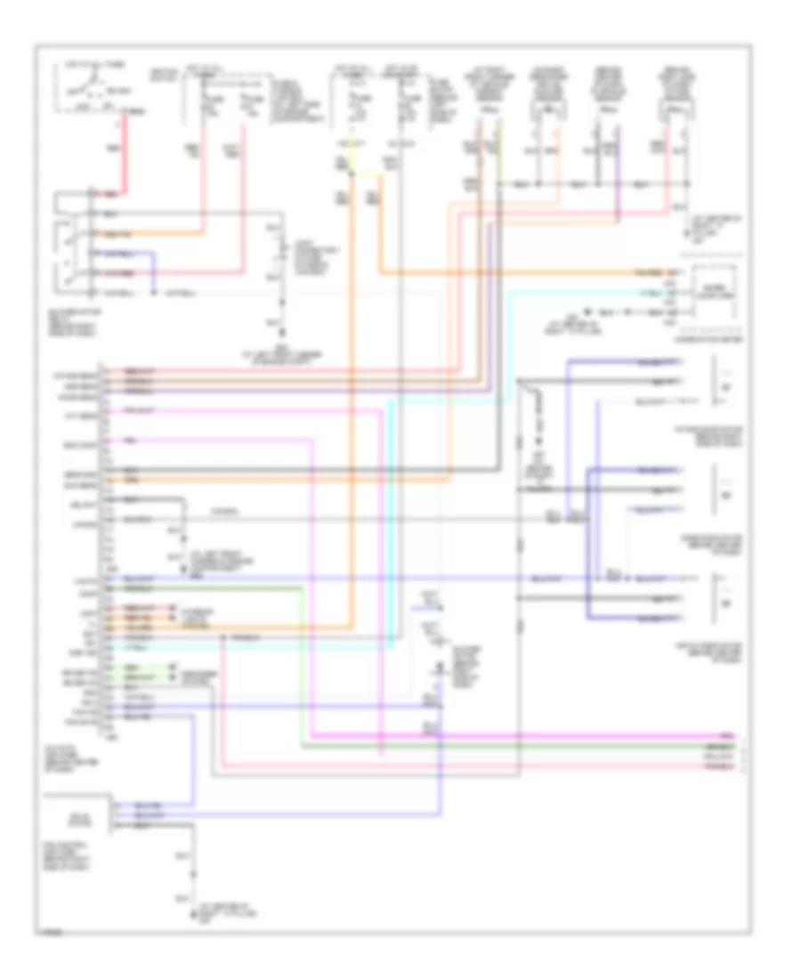
Automatic A/C Wiring Diagram, with Navigation (2 of 2) for Nissan Maxima SE 2003
List of elements for Automatic A/C Wiring Diagram, with Navigation (2 of 2) for Nissan Maxima SE 2003:
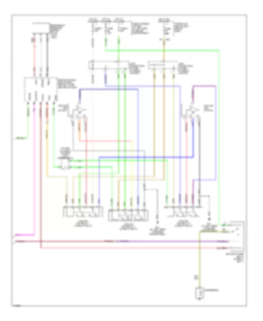
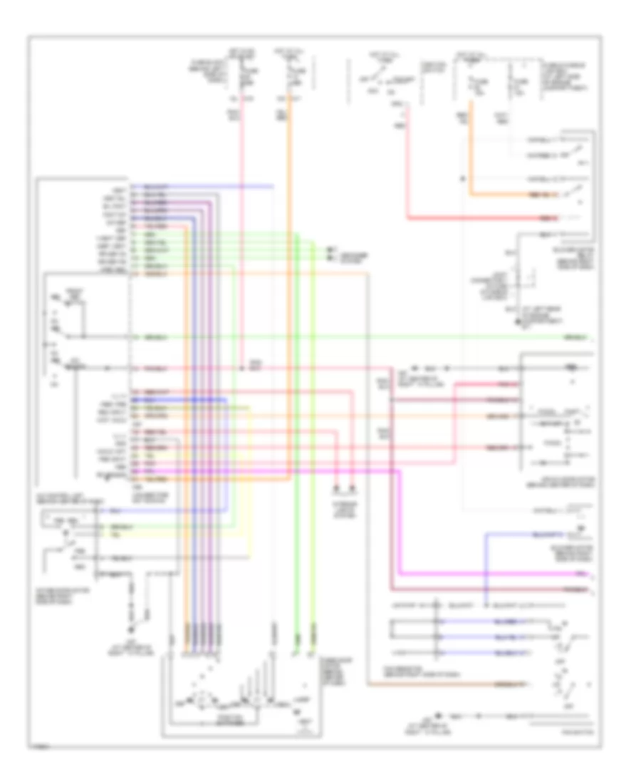
Automatic A/C Wiring Diagram, without Navigation (1 of 2) for Nissan Maxima SE 2003
List of elements for Automatic A/C Wiring Diagram, without Navigation (1 of 2) for Nissan Maxima SE 2003:
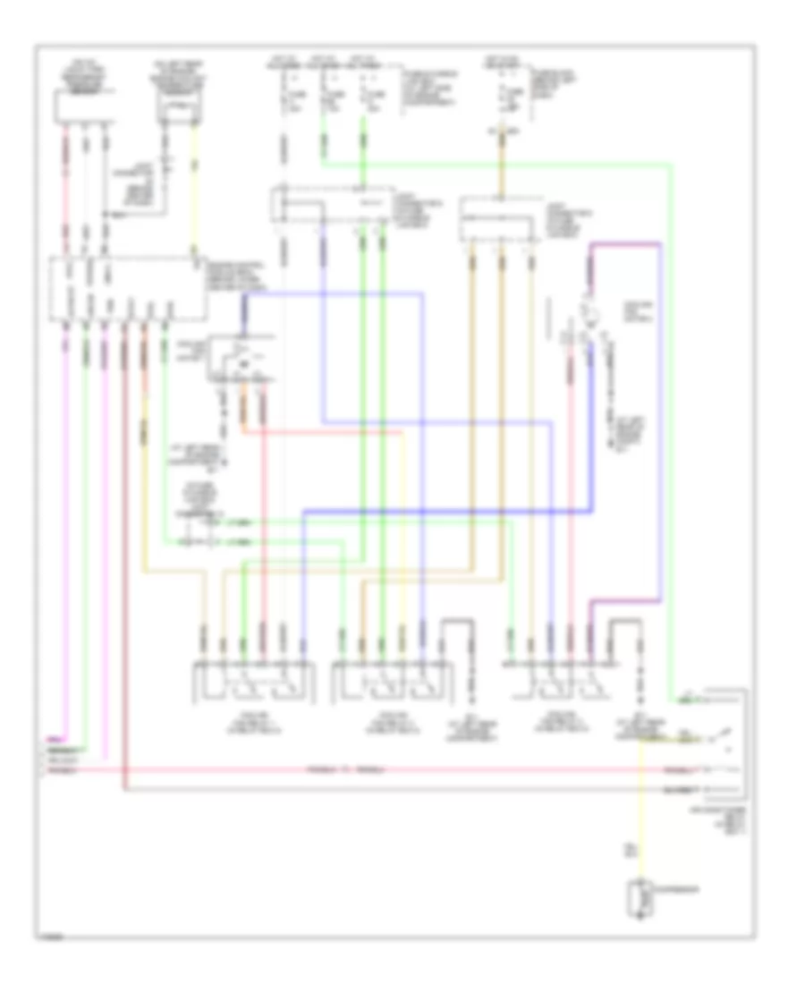
Automatic A/C Wiring Diagram, without Navigation (2 of 2) for Nissan Maxima SE 2003
List of elements for Automatic A/C Wiring Diagram, without Navigation (2 of 2) for Nissan Maxima SE 2003:
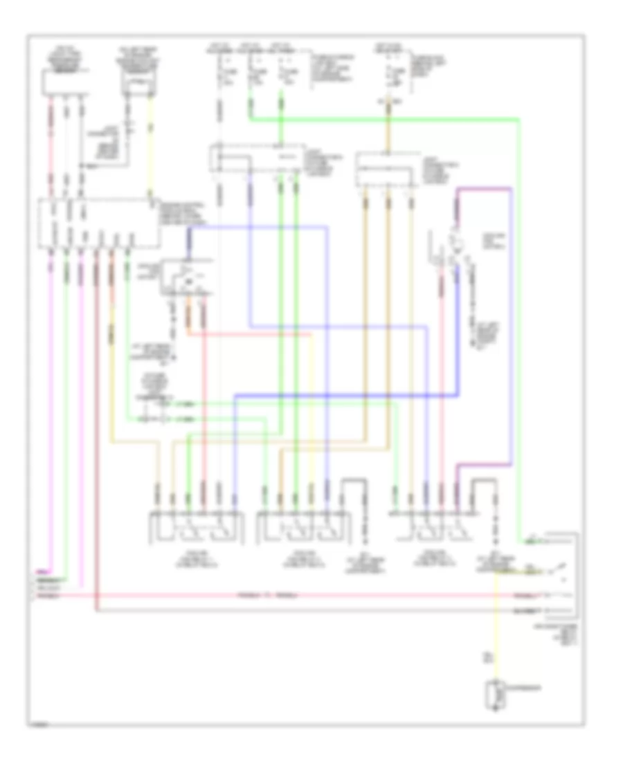
Manual A/C Wiring Diagram (1 of 2) for Nissan Maxima SE 2003
List of elements for Manual A/C Wiring Diagram (1 of 2) for Nissan Maxima SE 2003:
Manual A/C Wiring Diagram (2 of 2) for Nissan Maxima SE 2003
List of elements for Manual A/C Wiring Diagram (2 of 2) for Nissan Maxima SE 2003: