AIR CONDITIONING
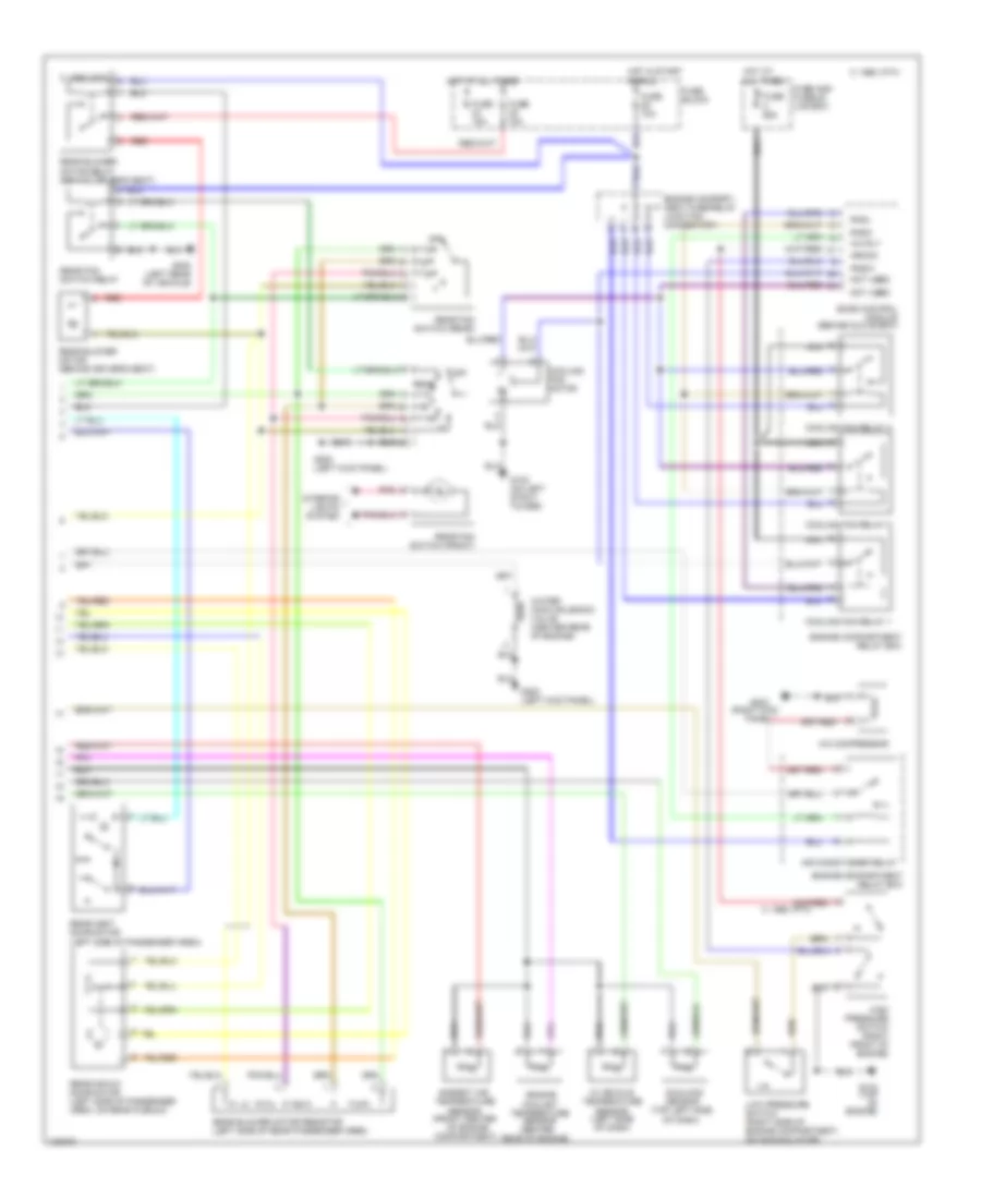
A/C Wiring Diagram, Auto A/C (1 of 2) for Nissan Quest GLE 1998

List of elements for A/C Wiring Diagram, Auto A/C (1 of 2) for Nissan Quest GLE 1998:
- (right kick panel) g203
- Acc
- All times
- Ambient air temp
- C 1995 vftc
- C 1995 vftc 1995 vftc c
- E/m switch
- Eatc module
- Eatc unit (center of dash)
- F/r door
- F/r door actuator
- Floor/panel
- Front air mix door motor (behind right side of dash, on plenum)
- Front blower motor
- Front blower motor relay
- Front blower speed control unit (right side of dash)
- Front intake door motor (behind right side of dash, on plenum)
- Frt blend door
- Frt blend door (cool)
- Frt blend door (warm)
- Frt blo motor relay
- Frt blower motor
- Fuse block
- Fuse 10a
- Fuse 20a
- Fuse 28 20a
- Fuse 7.5a
- Fuse and fusible link box
- Fuse block
- Fuse d 65a
- G200 (left kick panel)
- Ground
- Heater coolant temp
- Hot at
- Hot at all times
- Hot in run
- Ignition
- Ignition switch
- Illumination
- In car temp sensor
- Instrument cluster
- Interior lights system
- Lo pressure
- Lock
- Mode actuator
- Mode door motor (behind center of dash)
- Nca
- Off
- Pnk
- Position switches
- Power
- Rea water vlv sol
- Rear a/c control unit
- Rear blend dr act
- Rear vent door act
- Rr blend door
- Rr blower motor
- Rr blower motor relay
- Rr blw motor sw
- Rr cc panel
- Rr cc power
- Rr cc switch (frt)
- Rr climate ctrl panel
- Run
- Sensor power
- Start
- Sunload sensor
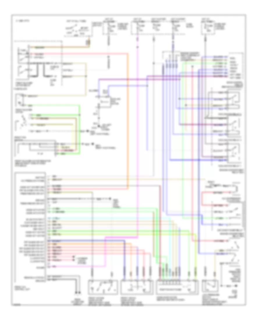
A/C Wiring Diagram, Auto A/C (2 of 2) for Nissan Quest GLE 1998
List of elements for A/C Wiring Diagram, Auto A/C (2 of 2) for Nissan Quest GLE 1998:
- (center
- (front center
- (right kick
- (top left side of dash)
- 1995 vftc c
- A/c compressor
- A/c rly
- Air conditioner relay
- Ambient air temperature
- Arcon
- C 1995 vftc
- Compartment)
- Cooling fan motor
- Cooling fan relay 1
- Cooling fan relay 2
- Cooling fan relay 3
- Eccs control module (behind glove box)
- Engine compart- ment fuse/relay junction connector 1
- Engine compartment relay box
- Engine coolant temperature sensor
- Fuse 10a
- Fuse 15a
- Fuse and fusible link box
- Fuse block
- Fuse c 65a
- G102 (on left strut tower)
- G134 (top of engine)
- G200 (left kick panel)
- G203
- G400 (left rear of vehicle)
- High pressure switch (right front of engine)
- Hot at all times
- Hot in start or run
- In vehicle temperature sensor (left side of dash)
- Interior lights system
- Low pressure switch (right side of engine compartment, on accumulator)
- Nca
- Not used
- Of engine
- Off
- Panel)
- Pdsw
- Pnk
- Radh
- Radl
- Rear
- Rear air mix door motor (left side of passenger area, on rear plenum)
- Rear blower motor (behind driver's seat)
- Rear blower motor relay (behind driver's seat)
- Rear blower motor resistor (left side of rear passenger area)
- Rear fan switch (front)
- Rear fan switch (rear)
- Rear fan switch relay
- Rear of engine)
- Rear vent door motor (left side of passenger area)
- Red
- Sensor
- Sunload sensor
- Water cock solenoid valve (center rear of engine)
A/C Wiring Diagram, Manual A/C for Nissan Quest GLE 1998
List of elements for A/C Wiring Diagram, Manual A/C for Nissan Quest GLE 1998:
- (on left
- (right
- A/c compressor clutch coil
- A/c press switches
- A/c rly
- Acc
- Air conditioner relay
- All times
- Arcon
- Bi-lev/flr input
- C 1995 vftc
- Cooling fan motor
- Cooling fan relay 1
- Cooling fan relay 2
- Cooling fan relay 3
- Def input
- Eccs control module (behind glove box)
- Engine compart- ment fuse/relay junction connector 1
- Engine compartment relay box
- Flr,flr/def input
- Flr/def or def input
- Fresh/recirc dr act
- Front a/c control unit
- Front air mix door motor (behind right side of dash, on plenum)
- Front blower motor
- Front blower motor relay
- Front blower motor resistor (behind right side of dash, in plenum)
- Front fan switch
- Front intake door motor (behind right side of dash, on plenum)
- Frt blend dr act
- Frt blend dr mtr act
- Frt blower mtr ctrl
- Fuse 10a
- Fuse 20a
- Fuse 28 20a
- Fuse 7.5a
- Fuse and fusible link box
- Fuse block
- Fuse c 65a
- Fuse d 65a
- G102
- G134 (top of engine)
- G200 (left kick panel)
- G203
- G203 (right kick panel)
- Ground
- High pressure switch (right front of engine)
- Hot at
- Hot at all times
- Hot in start or run
- Ignition
- Ignition switch
- Illumination
- Interior lights system
- Kick
- Lock
- Low pressure switch (right side of engine compartment, on accumulator)
- Mode act motor
- Mode act sig return
- Mode actuator
- Mode door motor (behind center of dash)
- Nca
- Not used
- Off
- Panel)
- Pdsw
- Pnk
- Position switches
- Power
- Radh
- Radl
- Rear a/c-heater circuit
- Rear blw mtr sw
- Run
- Start
- Strut
- Tower)
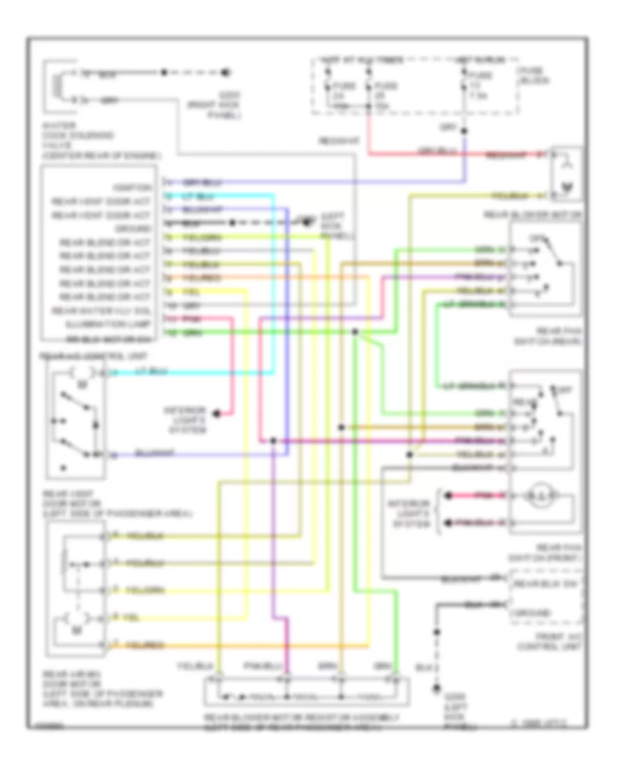
Rear A/C Wiring Diagram, Manual A/C for Nissan Quest GLE 1998
List of elements for Rear A/C Wiring Diagram, Manual A/C for Nissan Quest GLE 1998:
- (left kick panel)
- C 1995 vftc
- Front a/c control unit
- Fuse 15a
- Fuse 7.5a
- Fuse block
- G200
- G200 (left kick panel)
- G203 (right kick panel)
- Ground
- Hot at all times
- Hot in run
- Ignition
- Illumination lamp
- Interior lights system
- Off
- Pnk
- Rear
- Rear a/c control unit
- Rear air mix door motor (left side of passenger area, on rear plenum)
- Rear blend dr act
- Rear blower motor
- Rear blower motor resistor assembly (left side of rear passenger area)
- Rear blw sw
- Rear fan switch (front)
- Rear fan switch (rear)
- Rear vent door act
- Rear vent door motor (left side of passenger area)
- Rear water vlv sol
- Rr blw motor sw
- Water cock solenoid valve (center rear of engine)