AIR CONDITIONING
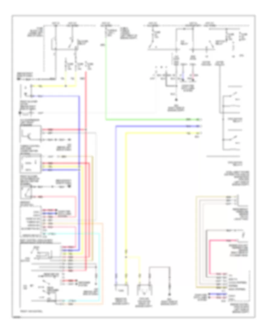
Manual A/C Wiring Diagram for Nissan Versa SL 2008
List of elements for Manual A/C Wiring Diagram for Nissan Versa SL 2008:
- (behind right side of dash) m61
- A/c comp
- A/c compressor (left front of engine)
- A/c ind
- A/c relay
- A/c switch
- Aircon ind out
- Aircon sw
- Avcc2 (pdpres)
- Blower fan sw
- Blower relay
- Body control module (bcm) (behind right side of dash)
- Can-h
- Can-l
- Computer data lines system
- Cooling fan motor (front of engine compt)
- Cooling fan relay-1
- Cooling fan relay-3
- Cpu
- Defogger system
- Defrost a/c switch
- E16
- E24 (right side of engine compt)
- E43
- E44
- E46
- E48
- Engine control module (ecm) (left side of engine compt)
- Engine coolant temperature sensor (right rear of cylinder head)
- F11
- Fan switch
- Front air control
- Front blower motor (behind right side of dash)
- Front blower motor resistor (behind center of dash)
- Fuse & fusible link box (left front of engine compt)
- Fuse 10a
- Fuse 15a
- Fuse 20a
- Fuse block (j/b) (under left end of dash)
- Fusible link j 50a
- Gnd (pwr)
- Gnd (sig)
- Gnd-tw
- Gnda (pdpres)
- Hot at all times
- Hot in on
- Hot in on or start
- Ignition relay
- Intelligent power distribution module engine room (ipdm e/r) (left side of engine compt)
- M18
- M19
- M57 (behind left end of dash)
- Mode a/c on
- Motor fan-high
- Motor fan-low
- Off
- Pdpres
- Pnk
- Rear def ind
- Rear defogger switch
- Red
- Refrigerant pressure sensor (on a/c liquid tank)
- Resistor (front of engine compt)
- Thermo control amplifier (under center of dash)
- Thermo sw
 English