ANTI-LOCK BRAKES
Anti-lock Brake Wiring Diagrams for Mitsubishi Galant GTZ 2000
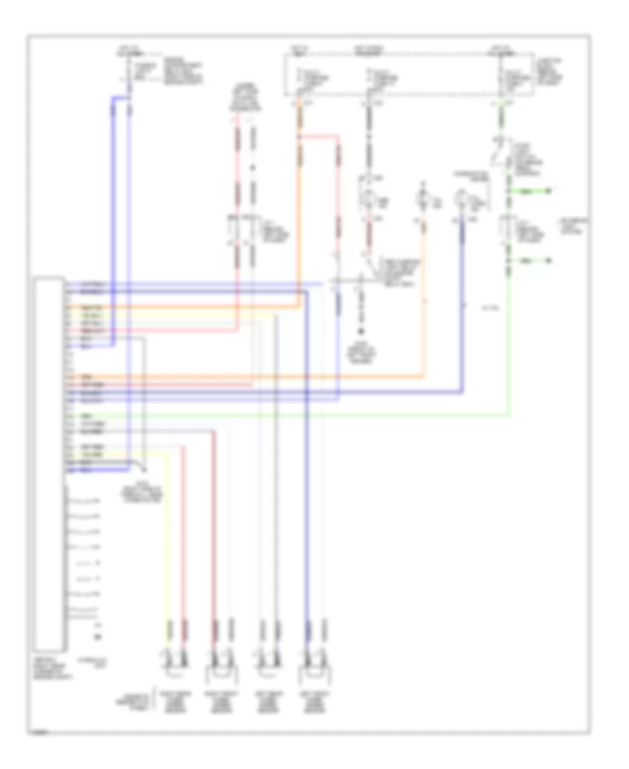
List of elements for Anti-lock Brake Wiring Diagrams for Mitsubishi Galant GTZ 2000:
- (inside of respective wheel)
- (under left side of dash) data link connector
- Abs ecu (right rear corner of engine compt)
- Abs ind
- Abs warning light relay (on engine compt relay box)
- C29
- C30
- C77
- C78
- Combination meter
- Engine compartment relay box (right side of engine compt)
- Exterior light system
- Fusible link 5 50a
- G100 (front of left front fender)
- G123 (right side of firewall, near wiper motor)
- Hot at all times
- Hot in run
- Hot in run or start
- Hydraulic unit
- J/c 1 (behind left side of dash)
- Junction block (behind left side of dash)
- Left front wheel speed sensor
- Left rear wheel speed sensor
- Multi- purpose fuse 13 10a
- Multi- purpose fuse 3 15a
- Multi- purpose fuse 9 10a
- Nca
- Right front wheel speed sensor
- Right rear wheel speed sensor
- Stop- light switch (on brake pedal support)
- Tcl ind
- Tcl warn ind
- W/ tcl
 English