ANTI-LOCK BRAKES
Anti-lock Brakes Wiring Diagram for Mitsubishi Outlander SE 2006
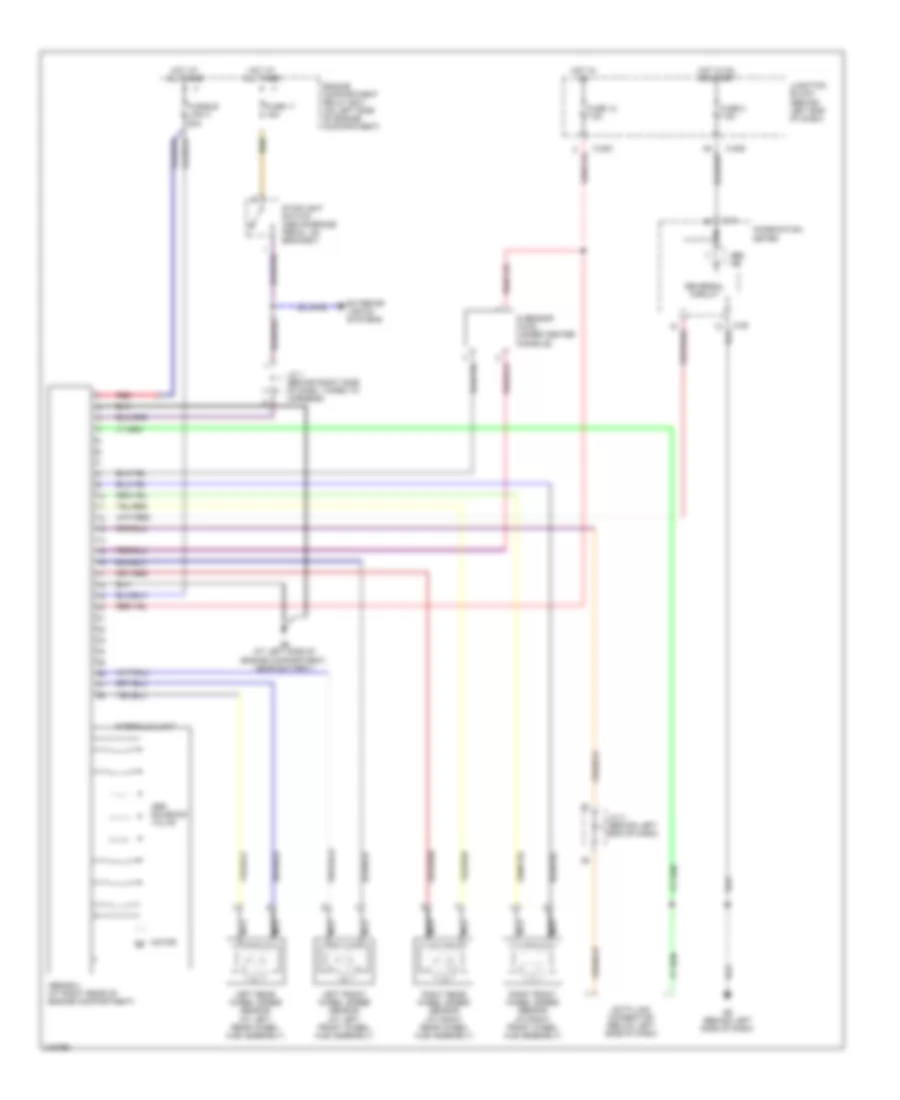
List of elements for Anti-lock Brakes Wiring Diagram for Mitsubishi Outlander SE 2006:
- Abs ind
- Abs solenoid valve
- Abs-ecu (at right rear of engine compartment)
- C-04
- C-05
- C-202
- C-205
- Combination meter
- Data link connector (below left side of dash)
- Engine compartment relay box (on left side of engine compartment)
- Exterior lights systems
- Fuse 11 15a
- Fuse 12 7.5a
- Fuse 2 7.5a
- Fusible link 3 60a
- G sensor (awd) (under center console)
- G6 (behind left side of dash)
- G9 (at left side of engine compartment, near battery)
- Hot at all times
- Hot in on
- Hot in on or start
- Hydraulic unit
- J/c 1 (behind right side of dash, taped to harness)
- J/c 3 (behind left end of dash)
- Junction block (behind left end of dash)
- Left front wheel speed sensor (at left front wheel hub assembly)
- Left rear wheel speed sensor (at left rear wheel hub assembly)
- Motor
- Nca
- Red
- Reversal circuit
- Right front wheel speed sensor (at right front wheel hub assembly)
- Right rear wheel speed sensor (at right rear wheel hub assembly)
- Stoplight switch (above brake pedal, on bracket)
 English