ANTI-LOCK BRAKES
Anti-lock Brake Wiring Diagrams for Nissan Altima GLE 2000
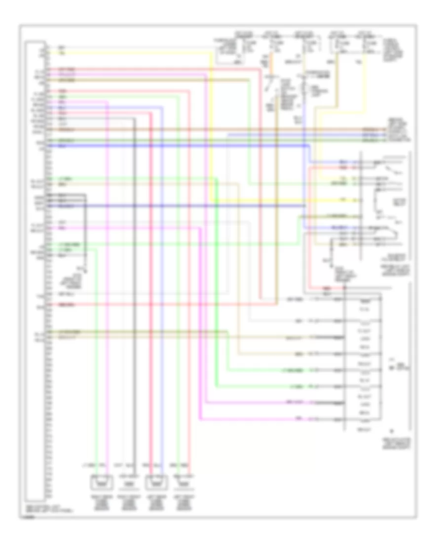
List of elements for Anti-lock Brake Wiring Diagrams for Nissan Altima GLE 2000:
- (behind left side of dash) (consult) data link connector
- 16n
- 87a
- Abs actuator (left rear of engine compt)
- Abs control unit (behind left kick panel)
- Abs motor
- Abs relay unit (left side of engine compt)
- Abs warning lamp
- Bls
- Combination meter
- Diag l
- Fl gnd
- Fl in
- Fl out
- Fl ss
- Fr gnd
- Fr in
- Fr out
- Fr ss
- Fuse & fusible link box (left side of engine compt)
- Fuse 10a
- Fuse 15a
- Fuse block (under left side of dash)
- Fuse f 40a
- Fuse h 40a
- G100 (front of left front fender)
- Gnd
- Gnd1
- Gnd2
- Hot at all times
- Hot in on or start
- Left front wheel speed sensor
- Left rear wheel speed sensor
- Motor relay
- Nca
- Pnk
- Red
- Right front wheel speed sensor
- Right rear wheel speed sensor
- Rl gnd
- Rl in
- Rl out
- Rl ss
- Rr gnd
- Rr in
- Rr out
- Rr ss
- Rxd
- Sila
- Solenoid valve relay
- Stop lamp switch (on bracket above brake pedal)
- Txd
 English