ANTI-LOCK BRAKES
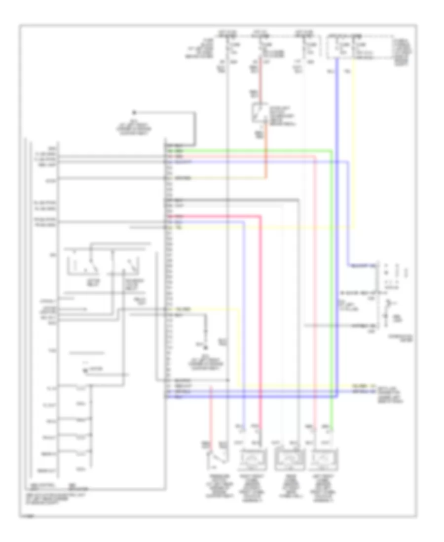
2.4L
2.4L, Anti-lock Brakes Wiring Diagram, 2WD for Nissan Frontier S/C 2003

List of elements for 2.4L, Anti-lock Brakes Wiring Diagram, 2WD for Nissan Frontier S/C 2003:
- (2.4l)
- (3.3l)
- (4 door) (2 door)
- (under left side of dash)
- 11p
- 30a
- Abs actuator
- Abs actuator & electric unit (at left rear corner of engine compt)
- Abs control unit
- Abs lamp
- Combination meter
- Data link connector
- E12 (at left front corner of engine compartment)
- E14 (at left front corner of engine compartment)
- E49
- Fl in
- Fl out
- Fl ss (gnd)
- Fl ss (pwr)
- Fr in
- Fr out
- Fr ss (gnd)
- Fr ss (pwr)
- Fuse & fusible link box (at right side of engine compt)
- Fuse 10a
- Fuse 20a 10a
- Fuse block (at left side of dash, behind cover)
- Fuse c 40a
- Fuse d 40a
- Gnd
- Hot at all times
- Hot in on or start
- Ign
- Left front wheel sensor (on left front wheel knuckle assembly)
- M14 (at left ``a" pillar)
- M26
- M27
- M38
- M39
- Motor
- Motor monitor
- Motor relay
- Mtr rly
- Pnk
- Pressure switch (at left rear corner of engine compartment)
- Rear in
- Rear out
- Rear wheel sensor (at right rear wheelwell)
- Red
- Relay unit
- Right front wheel sensor (on right front wheel knuckle assembly)
- Rl ss (gnd)
- Rl ss (pwr)
- Rxd
- Sol rly
- Solenoid valve relay
- Stop
- Stoplight switch (on bracket, above brake pedal)
- Txd
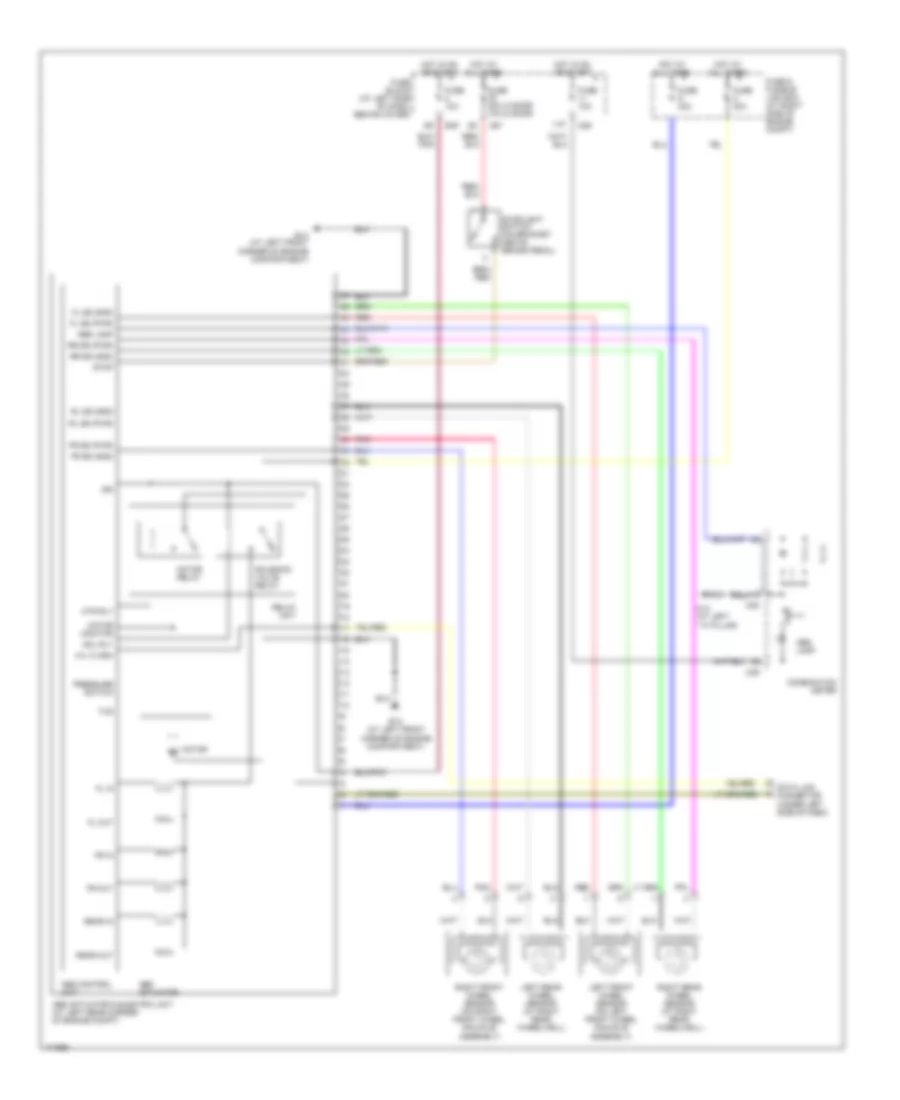
3.3L
3.3L, Anti-lock Brakes Wiring Diagram, 2WD for Nissan Frontier S/C 2003
List of elements for 3.3L, Anti-lock Brakes Wiring Diagram, 2WD for Nissan Frontier S/C 2003:
- (2.4l)
- (3.3l)
- (4 door) (2 door)
- (under left side of dash)
- 11p
- 30a
- Abs actuator
- Abs actuator & electric unit (at left rear corner of engine compt)
- Abs control unit
- Abs lamp
- Combination meter
- Data link connector
- E12 (at left front corner of engine compartment)
- E14 (at left front corner of engine compartment)
- E49
- Fl in
- Fl out
- Fl ss (gnd)
- Fl ss (pwr)
- Fr in
- Fr out
- Fr ss (gnd)
- Fr ss (pwr)
- Fuse & fusible link box (at right side of engine compt)
- Fuse 10a
- Fuse 20a 10a
- Fuse block (at left side of dash, behind cover)
- Fuse c 40a
- Fuse d 40a
- Gnd
- Hot at all times
- Hot in on or start
- Ign
- Left front wheel sensor (on left front wheel knuckle assembly)
- M14 (at left ``a" pillar)
- M26
- M27
- M38
- M39
- Motor
- Motor monitor
- Motor relay
- Mtr rly
- Pnk
- Pressure switch (at left rear corner of engine compartment)
- Rear in
- Rear out
- Rear wheel sensor (at right rear wheelwell)
- Red
- Relay unit
- Right front wheel sensor (on right front wheel knuckle assembly)
- Rl ss (gnd)
- Rl ss (pwr)
- Rxd
- Sol rly
- Solenoid valve relay
- Stop
- Stoplight switch (on bracket, above brake pedal)
- Txd
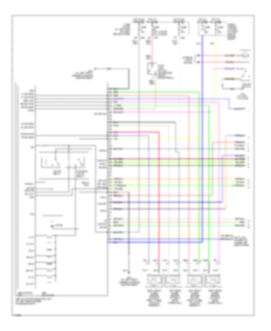
3.3L, Anti-lock Brakes Wiring Diagram, 4WD without Dynamic Stability Control for Nissan Frontier S/C 2003
List of elements for 3.3L, Anti-lock Brakes Wiring Diagram, 4WD without Dynamic Stability Control for Nissan Frontier S/C 2003:
- (4 door) (2 door)
- 11p
- Abs actuator
- Abs actuator & electric unit (at left rear corner of engine compt)
- Abs control unit
- Abs lamp
- Combination meter
- Data link connector (under left side of dash)
- E12 (at left front corner of engine compartment)
- E14 (at left front corner of engine compartment)
- E49
- Fl in
- Fl out
- Fl ss (gnd)
- Fl ss (pwr)
- Fr in
- Fr out
- Fr ss (gnd)
- Fr ss (pwr)
- Fuse & fusible link box (at right side of engine compt)
- Fuse 10a
- Fuse 20a 10a
- Fuse block (at left side of dash, behind cover)
- Fuse c 30a
- Fuse d 40a
- Hot at all times
- Hot in on or start
- Ign
- Left front wheel sensor (on left front wheel knuckle assembly)
- Left rear wheel sensor (at right rear wheelwell)
- M14 (at left ``a" pillar)
- M26
- M27
- M38
- M39
- Motor
- Motor monitor
- Motor relay
- Mtr rly
- Pnk
- Pressure switch
- Rear in
- Rear out
- Red
- Relay unit
- Right front wheel sensor (on right front wheel knuckle assembly)
- Right rear wheel sensor (at right rear wheelwell)
- Rl ss (gnd)
- Rl ss (pwr)
- Rr ss (gnd)
- Rr ss (pwr)
- Sol rly
- Solenoid valve relay
- Stop
- Stoplight switch (on bracket above brake pedal)
- Txd
- W/l flash
3.3L, Anti-lock Brakes Wiring Diagram, with Dynamic Stability Control (1 of 2) for Nissan Frontier S/C 2003
List of elements for 3.3L, Anti-lock Brakes Wiring Diagram, with Dynamic Stability Control (1 of 2) for Nissan Frontier S/C 2003:
- (2 door)
- (4 door)
- 10a
- 11p
- 4wd sw
- Abs actuator
- Abs actuator & electric unit (at left rear corner of engine compt)
- Abs control unit
- Abs lamp
- Can-h
- Can-l
- Can2-h
- Can2-l
- Connector (under left side of dash)
- Dr1 gnd
- Dr1 sig
- Dr1 sns
- E12 (at left front corner of engine compartment)
- E14 (at left front corner of engine compartment)
- E49
- Fl in
- Fl out
- Fl ss (gnd)
- Fl ss (pwr)
- Fr in
- Fr out
- Fr ss (gnd)
- Fr ss (pwr)
- Fuse & fusible link box (at right side of engine compt)
- Fuse 10a
- Fuse 20a
- Fuse block (at left side of dash, behind cover)
- Fuse c 30a
- Fuse d 40a
- Gnd
- Gs gnd
- Gs sig
- Hot at all times
- Hot in on or start
- Ign
- Interior lights system
- L/s
- Left front wheel sensor (on left front wheel knuckle assembly)
- Left rear wheel sensor (at right rear wheelwell)
- M14 (at left ``a" pillar)
- M26
- M27
- Motor
- Motor monitor
- Motor relay
- Mtr rly
- Pnk
- Red
- Relay unit
- Right front wheel sensor (on right front wheel knuckle assembly)
- Right rear wheel sensor (at right rear wheelwell)
- Rl in
- Rl out
- Rl ss (gnd)
- Rl ss (pwr)
- Rr in
- Rr out
- Rr ss (gnd)
- Rr ss (pwr)
- Rxd
- Sol rly
- Solenoid valve relay
- Stop
- Stop light switch (on bracket, above brake pedal)
- Tcs slip
- Txd
- Vdc off
- Vdc off sw
- Vdc off switch
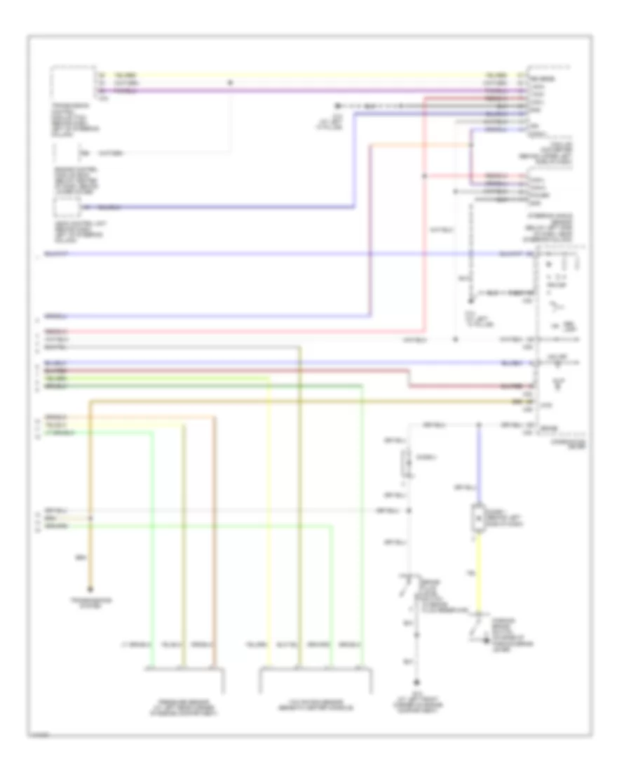
3.3L, Anti-lock Brakes Wiring Diagram, with Dynamic Stability Control (2 of 2) for Nissan Frontier S/C 2003
List of elements for 3.3L, Anti-lock Brakes Wiring Diagram, with Dynamic Stability Control (2 of 2) for Nissan Frontier S/C 2003:
- 4wd
- Abs lamp
- Ascd control unit (behind dash, left of steering column)
- Brake
- Brake fluid level switch (in brake fluid reservoir)
- Can-h
- Can-l
- Can-lan converter (behind upper left side of dash)
- Combination meter
- Diode 1 (behind left side of dash)
- Diode 4
- E12 (at left front corner of engine compartment)
- Engine control module (ecm) (below center of dash, behind lower cover)
- Gnd
- Ign
- Lan-8
- M14 (at left ``a" pillar)
- M38
- M39
- M78
- Of dash, near steering column)
- Parking brake switch (on base of parking brake lever)
- Power
- Pressure sensor (at left rear corner of engine compartment)
- Reverse
- Sensor (below left side
- Slip
- Steering angle
- Tach
- Transmission control module (tcm) (behind dash, left of steering column)
- Transmissions system
- Vdc off
- Yaw rate/g sensor (beneath center console)