ANTI-LOCK BRAKES
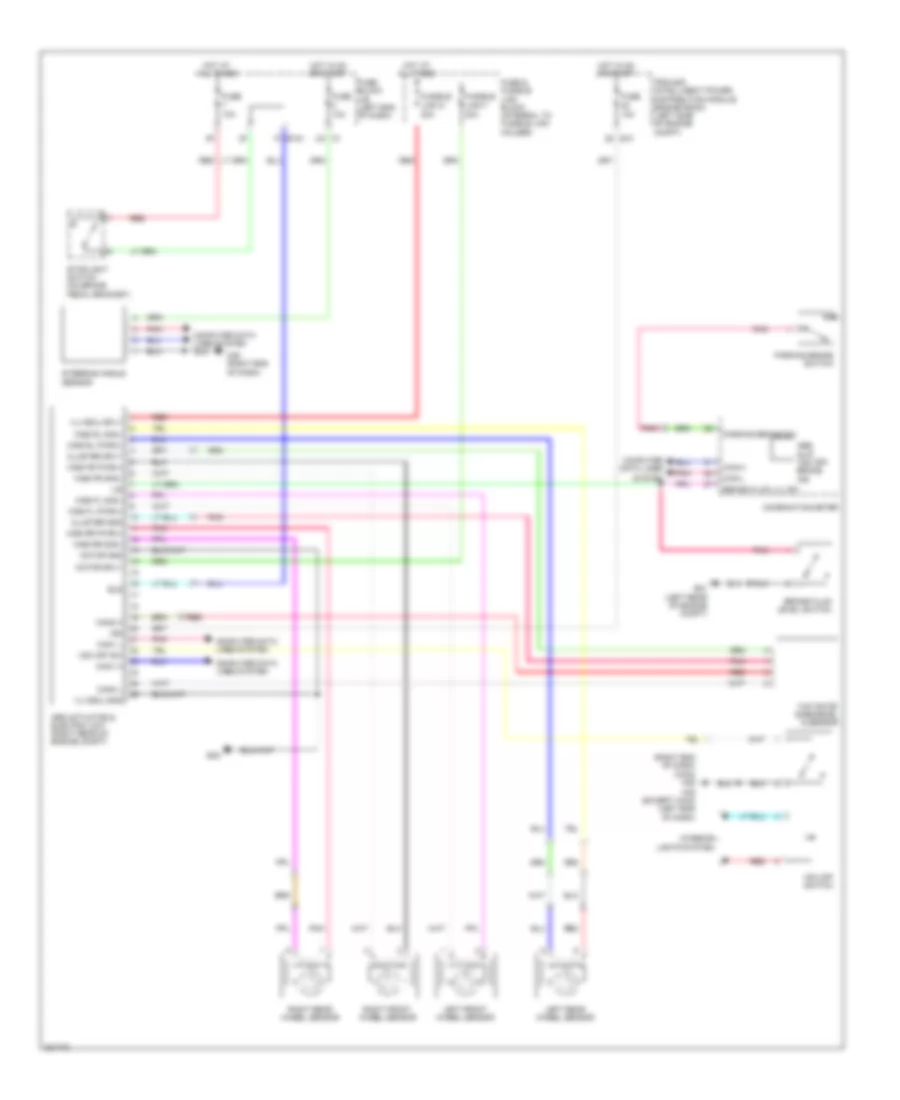
Anti-lock Brakes Wiring Diagram for Nissan Murano LE 2010
List of elements for Anti-lock Brakes Wiring Diagram for Nissan Murano LE 2010:
- (right end of dash) (awd) m35
- 10a
- 1f e103
- 20a
- 2a m1
- 30a
- Abs actuator & electric unit (right rear of engine compt)
- Abs, slip, vdc off, brake ind
- Bls
- Brake fluid level switch
- Brake fluid lvl sw
- Can-h
- Can-l
- Can1 h
- Can1 l
- Can2 h
- Can2 l
- Cluster gnd
- Cluster sply
- Combination meter
- Computer data lines
- Computer data lines system
- E10
- E21 (left rear of engine compt)
- E38
- Fuse
- Fuse & fusible link block (integral to fusible link holder)
- Fuse block j/b (left end of dash)
- Fusible link f
- Fusible link g
- Hot at all times
- Hot in on or start
- Ign
- Interior lights system
- Ipdm e/r (intelligent power distribution module engine room) (left side of engine compt)
- Left front wheel sensor
- Left rear wheel sensor
- Lis
- M35 (right end of dash)
- M76 (except awd) (left end of dash)
- Motor gnd
- Motor sply
- Parking brake sw
- Parking brake switch
- Pnk
- Red
- Right front wheel sensor
- Right rear wheel sensor
- Steering angle sensor
- Stoplight switch (on brake pedal bracket)
- System
- Vdc off sw
- Vdc off switch
- Vlv/ecu gnd
- Vlv/ecu sply
- Wss fl pwr(+)
- Wss fl sig(-)
- Wss fr pwr(+)
- Wss fr sig(-)
- Wss rl pwr(+)
- Wss rl sig(-)
- Wss rr pwr(+)
- Wss rr sig(-)
- Yaw rate/ side/decel g sensor
 English