ANTI-LOCK BRAKES
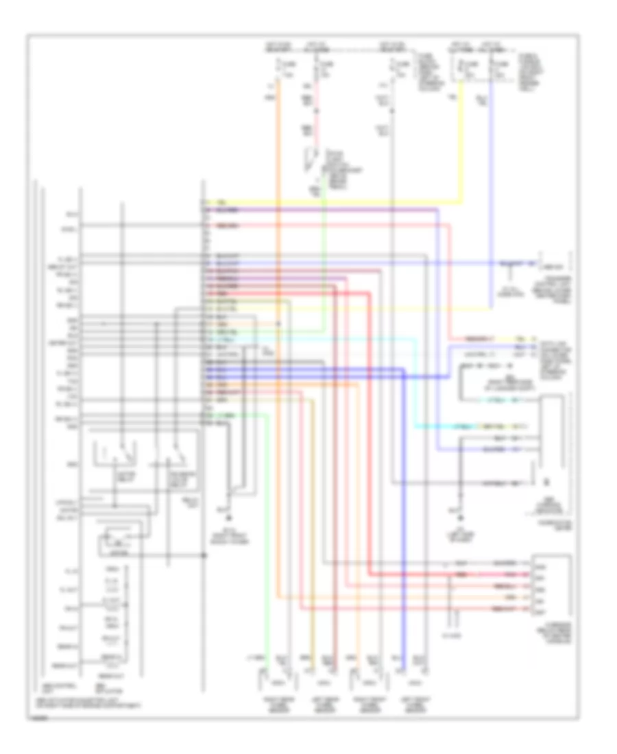
Anti-lock Brake Wiring Diagrams for Nissan Pathfinder SE 2002
List of elements for Anti-lock Brake Wiring Diagrams for Nissan Pathfinder SE 2002:
- 17u
- 39u
- Abs actuator
- Abs actuator & electric unit (on right side of engine compartment)
- Abs control unit
- Abs sig
- Abs st out
- Abs warning indicator
- B75 (right rear side of luggage compt)
- Bls
- Combination meter
- Data link connector (on lower dash panel, left of steering column)
- Diag l
- E112 (right front shock tower)
- Fl in
- Fl out
- Fl ss (+)
- Fl ss (-)
- Fr in
- Fr out
- Fr ss (+)
- Fr ss (-)
- Fuse & fusible link box (on right front fender well)
- Fuse 10a
- Fuse 7.5a
- Fuse block (behind dash, left of steering column)
- Fuse c 40a
- Fuse d 40a
- G sensor (below rear of center console)
- Gnd
- Gs1
- Gs2
- Gst
- Hot at all times
- Hot in on or start
- Ign
- Left front wheel sensor
- Left rear wheel sensor
- M4 (left side of dash)
- Meter out
- Motor
- Motor relay
- Mtr rly
- Pnk
- Rear in
- Rear out
- Red
- Relay unit
- Right front wheel sensor
- Right rear wheel sensor
- Rl ss (+)
- Rl ss (-)
- Rr ss (+)
- Rr ss (-)
- Rxd
- Sig
- Sila
- Sol rly
- Solenoid valve relay
- Stop light switch (on bracket above brake pedal)
- Transfer control unit (behind lower center dash panel)
- Txd
- Vcc
- W/ 4wd
- W/ all mode 4wd
 English