ANTI-LOCK BRAKES
Anti-lock Brake Wiring Diagrams for Nissan Quest GXE 1996
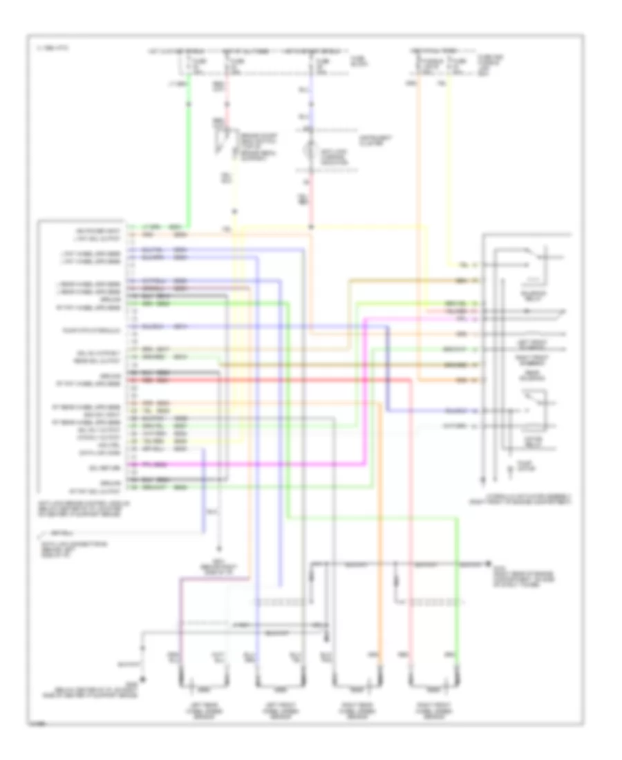
List of elements for Anti-lock Brake Wiring Diagrams for Nissan Quest GXE 1996:
- Anti-lock brake control module (below center of i/p, mounted on center i/p support brace)
- Anti-lock warning indicator
- Boo sw input
- Brake on/off (boo) switch (top of brake pedal support)
- Bs01
- Bs02
- Bs04
- Bs05
- Bs08
- Bs09
- Bs14
- Bs17
- Bs18
- Bs21
- Bs23
- Bs24
- Bs25
- Bs26
- Bs27
- Bs28
- Bs29
- Bs30
- Bs32
- Bs35
- C 1995 vftc
- Data link conn
- Data link connector #2 (behind left side of i/p)
- Eb10
- Eb20
- Eb34
- Fuse 10a
- Fuse 15a
- Fuse 20a
- Fuse and fusible link box
- Fuse block
- Fusible link b 30a
- G103 (right rear of engine compartment, on side of strut tower)
- G201 (behind right side of i/p)
- G206 (below center of i/p, on right side of center i/p support brace)
- Ground
- Hot at all times
- Hot in start or run
- Hydraulic actuator assembly (right front of engine compartment)
- Ign power input
- Ind ctrl
- Instrument cluster
- L fnt sol output
- L fnt wheel spd sens
- L rear wheel spd sens
- Left front solenoid
- Left front wheel speed sensor
- Left rear wheel speed sensor
- Motor relay
- Mtr rly output
- Nca
- Pump motor
- Pump mtr (hydraulic)
- Rear sol output
- Rear solenoid
- Red
- Right front solenoid
- Right front wheel speed sensor
- Right rear wheel speed sensor
- Rt fnt sol output
- Rt fnt wheel spd sens
- Rt rear wheel spd sens
- Sol return
- Sol rly output
- Sol rly/mtr rly
- Solenoid relay
 English