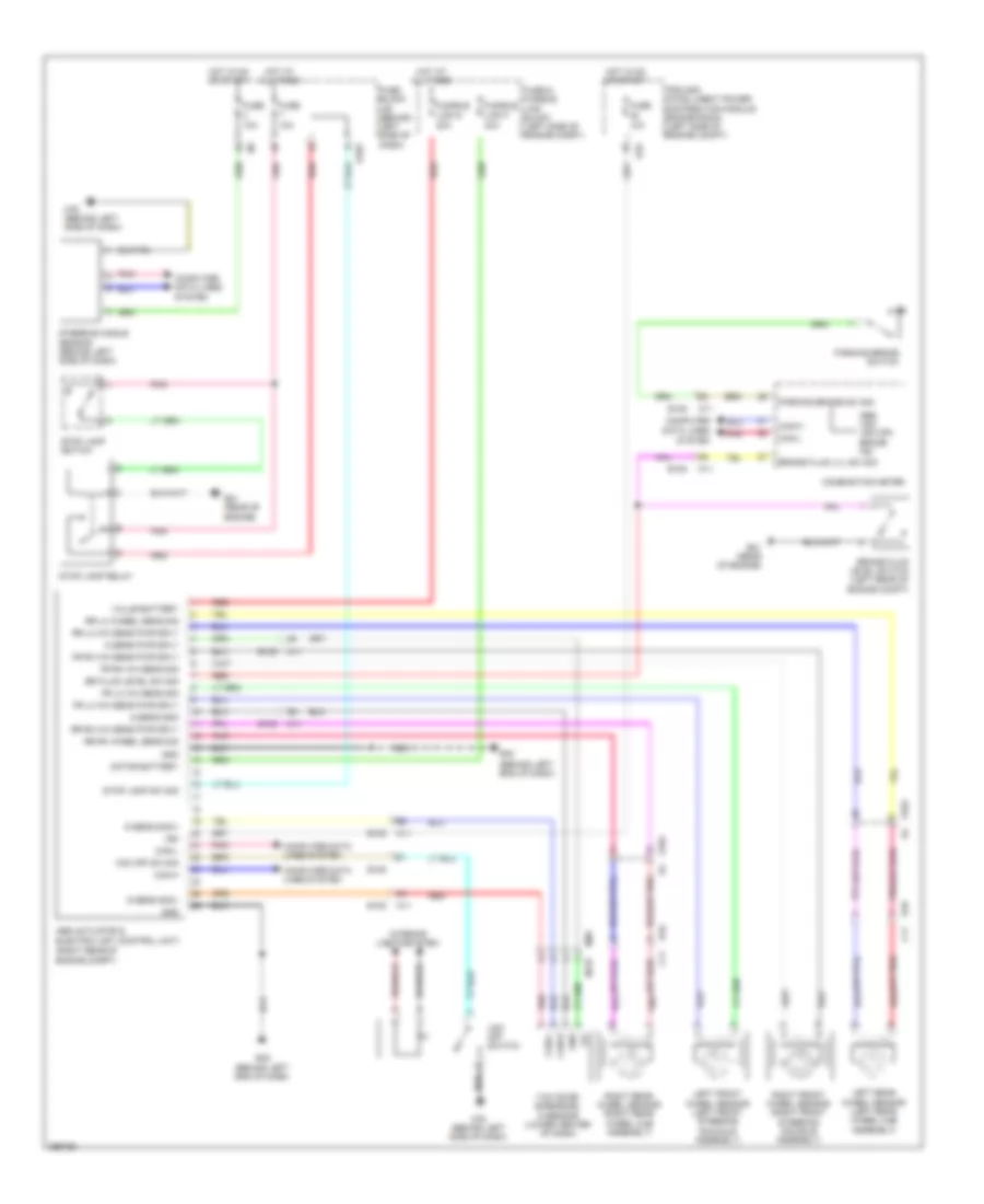
ANTI-LOCK BRAKES
Anti-lock Brakes Wiring Diagram for Nissan Quest SL 2014
List of elements for Anti-lock Brakes Wiring Diagram for Nissan Quest SL 2014:
- (behind left end of dash)
- (or pnk)
- (or red)
- (right rear of engine compt)
- 10a
- 12v
- 20a
- 30a
- Abs actuator & electric unit (control unit)
- Abs, vdc, vdc off, brake ind
- B10
- Br fluid level sw sig
- Brake fluid level switch (left rear of engine compt)
- Brake fluid lvl sw sig
- C11
- Can-h
- Can-l
- Combination meter
- Computer data lines
- Computer data lines system
- E10
- E103
- E104
- E105
- E21 (rear of engine)
- E42
- E42 (behind left end of dash)
- Fr lh wh sens pwr sply
- Fr lh wh sens sig
- Fr rh wh sens pwr sply
- Fr rh wh sens sig
- Fuse
- Fuse & fusible link block (left side of engine compt)
- Fuse block j/b (behind left side of dash)
- Fusible link f
- Fusible link g
- G sens gnd
- G sens pwr sply
- G sens sig(+)
- G sens sig(-)
- Gnd
- Hot at all times
- Hot in on or start
- Ign
- Interior lights system
- Ipdm e/r (intelligent power distribution module engine room) (left side of engine compt)
- Left front wheel sensor (left front steering knuckle assembly)
- Left rear wheel sensor (left rear wheel hub assembly)
- M11
- M137
- M58
- M76 (behind left side of dash)
- Motor battery
- Parking brake sw sig
- Parking brake switch
- Pnk
- Red
- Right front wheel sensor (right front steering knuckle assembly)
- Right rear wheel sensor (right rear wheel hub assembly)
- Rr lh wh sens pwr sply
- Rr lh wheel sens sig
- Rr rh wh sens pwr sply
- Rr rh wheel sens sig
- Steering angle sensor (behind left side of dash)
- Stop lamp relay
- Stop lamp sw sig
- Stop lamp switch
- System
- Value battery
- Vdc off sw sig
- Vdc off switch
- Yaw rate/ side/decel g sensor (lower center of dash)
 English