ANTI-LOCK BRAKES
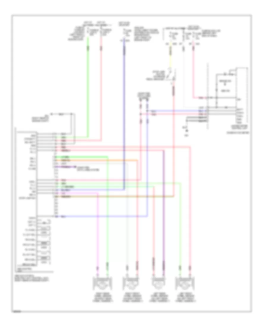
Anti-lock Brakes Wiring Diagram for Nissan Sentra S 2007
List of elements for Anti-lock Brakes Wiring Diagram for Nissan Sentra S 2007:
- Abs actuator & electric unit (control unit) (right rear of engine compt)
- Abs control unit
- Abs ind
- Batt
- Brake ind
- Can-h
- Can-l
- Combination meter
- Computer data lines system
- E39
- E41 (right rear of engine compt)
- E43
- Fl (+)
- Fl (-)
- Fl in sol
- Fl out sol
- Fr (+)
- Fr (-)
- Fr in sol
- Fr out sol
- Fuse & fusible link box (left front front of engine comp)
- Fuse 10a
- Fuse block (j/b) (behind left end of dash)
- Fusible link g 30a
- Fusible link h 30a
- Gnd
- Hot at all times
- Hot in on or start
- Ign
- Ipdm e/r (intelligent power distribution module engine room) (left front of engine comp)
- K-line
- Left front wheel sensor (on left front wheel assembly)
- Left rear wheel sensor (on left rear wheel assembly)
- M24
- M61
- Mot (+)
- Mot (-)
- Mtr batt
- Pnk
- Red
- Right front wheel sensor (on right front wheel assembly)
- Right rear wheel sensor (on right rear wheel assembly)
- Rl (+)
- Rl (-)
- Rl in sol
- Rl out sol
- Rr (+)
- Rr (-)
- Rr in sol
- Rr out sol
- Sol batt
- Stop lamp sw
- Stop lamp switch (on brake pedal bracket)
- Unified meter control unit
 English