ANTI-THEFT
Forced Entry Wiring Diagram for Mazda 3 i 2006

List of elements for Forced Entry Wiring Diagram for Mazda 3 i 2006:
- 5 door
- Btn fuse 40a
- D/lock 1 fuse 25a
- D/lock 2 fuse 15a
- Door key cylinder switch/ door lock-link switch/ left front door latch switch/left front door lock actuator (except left front door latch switch: in driver's door)
- Door lock relay
- Door unlock relay
- Driver's seat)
- Driver-side unlock relay
- Fuse & relay block (left rear of engine compt)
- G11 (below
- G12 (below center console)
- G2 (behind left headlight)
- G7 (behind left side of dash)
- G8 (behind right end of dash)
- Hood switch (on hood latch)
- Horns system
- Hot at all times
- J-01
- J-02
- J-03 c
- J-04
- J-05
- J-06
- Keyless control module (behind left side of dash)
- Left door lock switch
- Left rear door latch switch/ left rear door lock actuator
- Liftgate lock actuator (in liftgate)
- Lock
- Microcomputer
- Nca
- Passenger junction box (behind right side of dash)
- Red
- Reset
- Right door lock switch
- Right front door latch switch/ right front door lock actuator
- Right rear door latch switch/ right rear door lock actuator
- Room fuse 15a
- Set
- Trunk lid key cylinder switch (4 door) (rear center of trunk lid)
- Un- lock
- Unlock
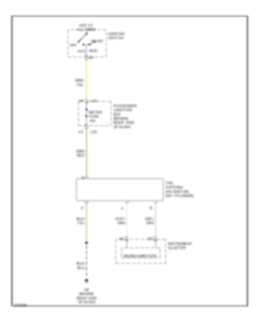
Immobilizer Wiring Diagram for Mazda 3 i 2006
List of elements for Immobilizer Wiring Diagram for Mazda 3 i 2006:
- Acc
- Coil antenna (on ignition key cylinder)
- G8 (behind right end of dash)
- Hot at all times
- Ig1
- Ignition switch
- Instrument cluster
- J-03
- Meter fuse 10a
- Microcomputer
- Off
- Passenger junction box (behind right side of dash)
- Run
- Start
 English