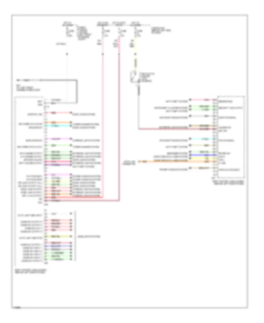
BODY CONTROL MODULES
Body Control Modules Wiring Diagram for Nissan Murano SE 2003
List of elements for Body Control Modules Wiring Diagram for Nissan Murano SE 2003:
- 12p
- 15a
- Acc
- Air conditioning system
- Anti-theft system
- Auto light sen input
- Auto light sen pwr
- Back door sw
- Bat
- Batt saver output
- Body control module (bcm) (behind left side of dash)
- Can h
- Can l
- Combi sw input 1
- Combi sw input 2
- Combi sw input 3
- Combi sw input 4
- Combi sw intput 5
- Combi sw out 4
- Combi sw output 1
- Combi sw output 2
- Combi sw output 3
- Combi sw output 5
- Comp on signal
- Computer data lines system
- Data link connector
- Defogger system
- Door locks system
- Door sw (as)
- Dr door sw
- Dr door unlock
- Dr lock output (all)
- E118
- E13 (at left front corner of eng comp)
- Exterior lights system
- Fan on signal
- Fuse & fusible link box (left front of engine compt)
- Fuse 10a
- Fuse block (behind left end of dash)
- Fuse f 50a
- Gnd
- Hazard sw
- Headlights system
- Hot at all times
- Hot in accy or on
- Hot in on or start
- Ign
- Instrument cluster system
- Interior lights system
- K line
- Key illum output
- Key sw
- Key switch and key lock solenoid
- Lh flasher output
- M21
- M35
- M36
- M37
- P/w pwr (bat)
- P/w pwr (rap)
- Pnk
- Power windows system
- Pwr win pwr (bat)
- Red
- Rh flasher output
- Room lamp output
- Rr def sw
- Rr wiper auto stop
- Rr wiper mtr output
- Security ind output
- Sensor gnd
- Step lamp output
- Wiper/washer system
 English