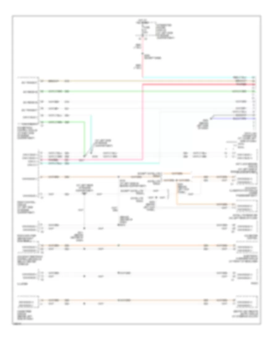
COMPUTER DATA LINES
Computer Data Lines Wiring Diagram for Mitsubishi Raider LS 2006
List of elements for Computer Data Lines Wiring Diagram for Mitsubishi Raider LS 2006:
- (at left rear of engine compartment) s107
- (at left side of engine compartment)
- (behind center of dash) s212
- A/c-heater control
- Anti-lock brakes module (at left side of engine compartment)
- Awal
- C1 c1
- Can b bus (+)
- Can b bus (-)
- Can c (+)
- Can c (-)
- Can c bus (+)
- Can c bus (-)
- Cluster
- D15
- D16
- D20
- D21
- D51
- D52
- D54
- D55
- D64
- D65
- Data link connector (at lower left side of dash)
- Electronic overhead module (at front of headliner)
- Except satellite radio
- Front control module (at left side of engine compartment)
- Fuse 20a
- G200 (behind left side of dash)
- Hands free module (behind left side of dash)
- Hot at all times
- Integrated power module (at left side of engine compartment)
- Occupant classification module (under passenger seat)
- Occupant restraint controller module (below center console)
- Pnk/red
- Powertrain control module (at right side of engine compartment)
- Radio
- Radio amplifier (behind right kick panel)
- Rwal
- S100
- S101
- S105 (at left side of engine compartment)
- S206 (except base)
- S211 (behind center of dash)
- S300 (behind left kick panel)
- S303 (behind left kick panel)
- Satellite radio
- Satellite receiver (on left rear of floor)
- Sci receive
- Sci transmit
- Sentry key remote entry module (at steering column)
 English