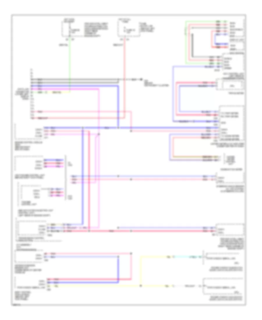
COMPUTER DATA LINES
Computer Data Lines Wiring Diagram for Nissan 350Z 2007
List of elements for Computer Data Lines Wiring Diagram for Nissan 350Z 2007:
- 2p/r
- A/t assembly (a/t) (on transmission)
- Abs actuator & electric unit (control unit) (left rear of engine compt)
- Air bag diagnosis sensor unit (under rear of center console)
- B105
- Body control module (bcm) (behind left kick panel)
- Bus shield
- Bus+
- Bus-
- Can-h
- Can-l
- Combination meter
- Cpu
- Data link connector (lower left side of dash)
- Ddl2
- Diag-k
- Display unit
- Engine control module (ecm) (behind right end of dash)
- F502
- Fuse 19 10a
- Fuse 89 10a
- Fuse block (j/b) (behind left kick panel)
- Hot at all times
- Hot in on or start
- Ipdm e/r (intelligent power distribution module engine room) (right rear corner of engine compt)
- K-line
- M30 (behind instrument cluster)
- M48
- M49
- M55
- M71
- M90
- Navi control unit (left rear of passenger compt)
- Navi switch
- Nca
- Pnk
- Power window main switch (door lock & unlock switch)
- Power window sub-switch (door lock & unlock switch)
- Pwr window serial link
- Red
- Rx (comb meter)
- Rx (trip meter)
- Shield
- Speed
- Steering angle sensor (w/ vdc system) (in steering column)
- Tcs/abs control unit
- Transmission control module (tcm)
- Triple meter
- Tx (comb meter)
- Tx (trip meter)
- Unified meter & a/c amplifier (under center of dash)
- Unified meter control unit
- Vdc/tcs/abs control unit (behind right kick panel)
- W/ vdc
- W/o vdc
 English