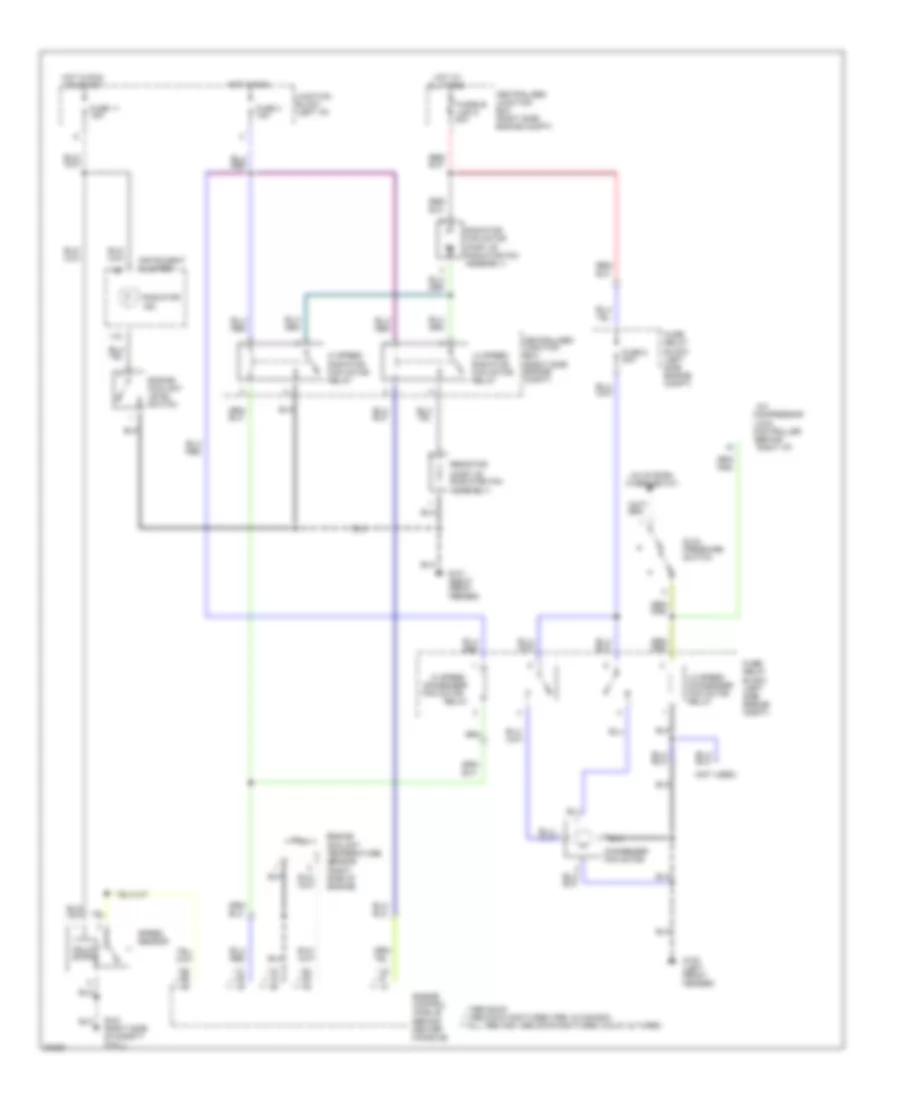
COOLING FAN
Cooling Fan Wiring Diagram for Mitsubishi 3000GT Spyder VR-4 1996
List of elements for Cooling Fan Wiring Diagram for Mitsubishi 3000GT Spyder VR-4 1996:
- (behind
- (not used)
- (part of radiator fan assembly)
- * ** ***
- ***all 1996 and 1995 dohc non-turbo (calif.) & turbo
- **1995 dohc non-turbo (fed. & canada)
- *1995 sohc
- A/c
- A/c system (thermostat)
- All times
- Centralized junction box (right side engine compt)
- Compressor
- Condenser fan motor
- Controller
- Dual pressure switch
- Engine control module (behind center console)
- Engine coolant level switch
- Engine coolant temperature sensor (right side of engine)
- Fuse 11 15a
- Fuse 3 10a
- Fuse 8 20a
- Fuse/ relay block (left side engine compt)
- Fusible link 5 40a
- G100 (left front fender)
- G101 (right front fender)
- G123 (right side of safety wall)
- Hi speed
- Hi speed radiator fan motor relay
- Hot at
- Hot in run
- Hot in run or start
- Instrument cluster
- Junction block (left i/p)
- Lo speed condenser fan motor relay
- Lo speed radiator fan motor relay
- Lock
- Radiator fan motor
- Radiator ind.
- Relay
- Resistor
- Right i/p)
- Solid state
- Speed sensor
 English