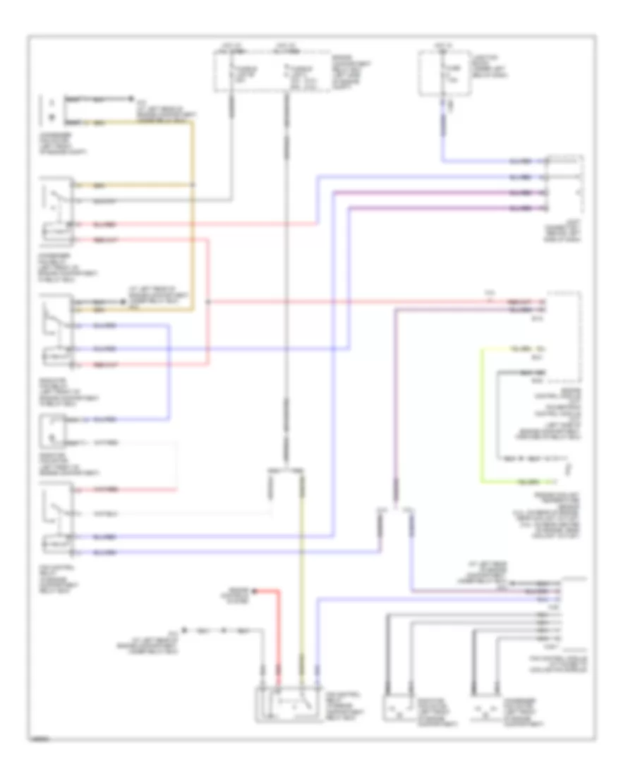
COOLING FAN
Cooling Fan Wiring Diagram for Mitsubishi Eclipse Spyder GS 2007
List of elements for Cooling Fan Wiring Diagram for Mitsubishi Eclipse Spyder GS 2007:
- (2.4l) (3.8l)
- (at left rear of engine compartment, under relay box) g12
- 2.4l
- 3.8l
- A-22
- A-22-1
- B-18
- B-20
- B-21
- C203
- Condenser fan motor (left front of engine compartment)
- Condenser fan motor (left front of engine compt)
- Condenser fan relay (left front of engine compartment, in relay box)
- Engine compartment relay box (left side of engine compt)
- Engine control module (m/t) powertrain control module (a/t) (left side of engine compartment, forward of relay box)
- Engine controls system
- Engine coolant temperature sensor (2.4l: on rear of engine, near coolant outlet) (3.8l: on rear center of engine, near coolant outlet)
- Fan control module (attached to cooling fan shroud)
- Fan control relay (in engine compartment relay box)
- Fuse 7.5a
- Fusible link 2 30a 50a
- Fusible link 26 20a
- G12 (at left rear of engine compartment, under relay box)
- Hot at all times
- Hot in on
- Joint connector 1 (behind left side of dash)
- Junction block (under left end of dash)
- Nca
- Radiator fan motor (left front of engine compartment)
- Radiator fan relay (left front of engine compartment, in relay box)
- Red
 English