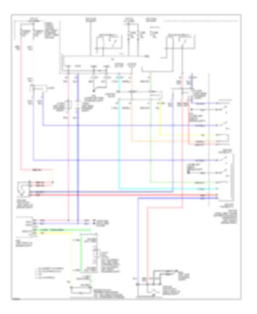
COOLING FAN
Cooling Fan Wiring Diagram for Nissan Altima Hybrid 2007
List of elements for Cooling Fan Wiring Diagram for Nissan Altima Hybrid 2007:
- (lower left side of engine compt) e9
- 2.5l california
- 2.5l california & 3.5l
- 2.5l except california
- 3.5l
- Can-h
- Can-l
- Computer data lines system
- Cooling fan motor 1 (left front of engine compt)
- Cooling fan motor 2 (right front of engine compt)
- Cooling fan relay 1
- Cooling fan relay 2
- Cooling fan relay 3
- Cpu
- E10
- E15 (lower left side of engine compt)
- E17
- E18
- E204 (left side of engine compt)
- E44
- E47
- E48
- Ecm (left front of engine compt)
- Engine coolant temperature sensor (2.5l: left rear of engine) (3.5l: upper rear of engine)
- F13
- Fuse & fusible link box (left front of engine compt, near ipdm e/r)
- Fuse 10a
- Fuse 15a
- Fusible link k 40a
- Fusible link m 40a
- Gnda-tw
- Hot at all times
- Hot in on or start
- Ig+
- Ignition relay 1
- Ipdm e/r (intelligent power distribution module engine room) (left side of engine compt)
- J/c e01
- J/c e02 (left rear of engine compt)
- J/c e03 (left rear of engine compt)
- J/c e04 (left side of engine compt)
- J/c f01 (3.5l) j/c f06 (2.5l california) (3.5l: left side of engine compt) (2.5l california: left front of engine compt)
- Junction block
- Mtr fan rly hi
- Mtr fan rly mid
- P-gnd
- Pnk
- Red
- S-gnd
 English