CRUISE CONTROL
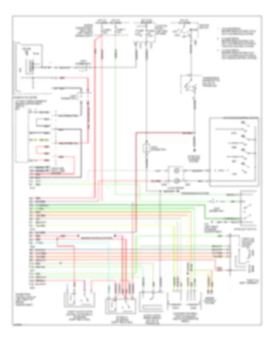
Cruise Control Wiring Diagram for Mitsubishi Endeavor LS 2005
List of elements for Cruise Control Wiring Diagram for Mitsubishi Endeavor LS 2005:
- (at right rear corner of engine compartment) abs/tcl ecu
- (main)
- (sub)
- Acc
- Accelerator pedal position sensor (above accelerator pedal)
- Auto-cruise control switch
- B-18
- B-19
- B-20
- B-21
- B-22
- C211
- C214
- C303
- C306
- C308
- Can
- Clock spring
- Combination meter
- Computer data lines system
- Cpu
- Cruise ind
- Engine compartment relay box (left side of engine compt)
- Engine controls system
- Fuse 11 15a
- Fuse 7.5a
- Fuse 9 20a
- G12 (left front of engine compartment)
- Hall ic
- Hot at all times
- Hot in on or start
- Ignition switch
- Joint connector 1
- Joint connector 3
- Joint connector 4
- Junction block (left end of dash)
- Lock
- Main
- Mfi relay (on engine compt relay box)
- Off
- On off
- Output shaft speed sensor (on top of transaxle)
- Powertrain control module (left front of engine compartment)
- Red
- Res
- Rheostat circuit
- Set
- Start
- Starting/ charging system
- Stoplight switch
- Throttle actuator control motor
- Throttle actuator control motor relay (on engine compt relay box)
- Throttle body assembly
- Transmission range switch (on top of transaxle)
- Transmissions system
- W/ electronic brake-force distribution, anti-lock braking system & active skid control system
- W/ electronic brake-force distribution, anti-lock braking system & traction control system
- W/o electronic brake-force distribution & anti-lock braking system
 English