CRUISE CONTROL
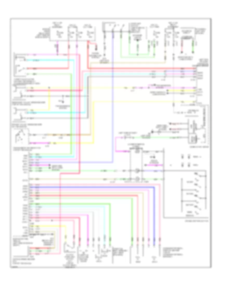
Cruise Control Wiring Diagram for Mitsubishi Outlander Sport ES 2011
List of elements for Cruise Control Wiring Diagram for Mitsubishi Outlander Sport ES 2011:
- (left end of dash) transaxle control module
- (left side of dash) j/c 2
- (main)
- (sub)
- (under steering wheel) clock spring
- 5vv
- A-16
- A-17
- Accelerator pedal position sensor (top of accelerator pedal bracket)
- Aps5
- Apse
- Apsm
- Apss
- B-26
- B-27
- Back
- Brk
- C-127
- C-130
- C-131
- C-28
- C-304
- C-312
- C-403
- C-410
- C-411
- C-412
- C-417
- Can
- Can drive circuit
- Can2
- Cancel
- Canh
- Canl
- Circuit face inter-
- Cirl
- Clutch inter lock switch (m/t) (top of clutch pedal assembly)
- Cnts
- Combination meter
- Computer data lines system
- Cpu
- Cruise control switch
- Cruise ind
- Distribution system
- Engine control module (left side of engine compt)
- Engine room relay box (left side of engine compt)
- Etacs-ecu (left end of dash)
- Etv+
- Etv-
- Exterior lights system
- Fuse 15a
- Fuse 20a
- Fuse 7.5a
- G14 (below left headlight assembly)
- G19 (left end of dash)
- G6 (left side of dash)
- Gndb
- Hall ic
- Hot at all times
- Hot w/ ig1 relay energized
- Hot w/ mfi relay energized
- Ill
- Inhn
- Interface circuit
- Led drive circuit
- Ntsw
- Off
- On/off
- Pnk
- Power
- Primary pulley speed sensor (on transaxle)
- Prms
- Red
- Res/acc
- Rsb
- Secondary pulley speed sensor (top of transaxle)
- Secs
- Set/cst
- Sgnd
- Sound systems
- Stoplight switch (above brake pedal, on bracket)
- Strl
- Sw-
- Throttle actuator control motor
- Throttle actuator control motor relay (in engine room relay box)
- Throttle body assembly (left rear of engine)
- Tps5
- Tpse
- Tpsm
- Tpss
- Transceiver circuit
- Transmission range switch (top of transaxle)
- Transmissions system
- V/s
- V/se
- Vehicle speed sensor (m/t) (top of transaxle)
- Vig2
 English