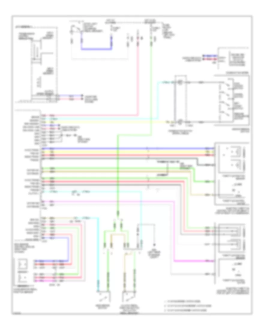
CRUISE CONTROL
Cruise Control Wiring Diagram for Nissan 370Z Touring 2014
List of elements for Cruise Control Wiring Diagram for Nissan 370Z Touring 2014:
- A/t assembly
- Accelerator pedal position sensor
- Aps1
- Aps2
- Ascd brake switch
- Ascd steering switch
- Ascdsw
- Avcc-tps-b1
- Avcc-tps-b2
- Avcc1-aps1
- Avcc2-aps2
- Bnc sw
- Brake
- Can comm line
- Can-h
- Can-l
- Cancel switch
- Close
- Clutch l
- Clutch pedal position switch (on clutch pedal bracket)
- Combination meter
- Combination switch (spiral cable)
- Computer data lines system
- Cruise, rev indicator (w/ m/t & synchrorev match mode)
- E103
- E106 m6
- E46 (left rear of engine compt)
- Ecm (engine control module) (right end of dash)
- Electric throttle control actuator (bank 1) (top of right cylinder bank)
- Electric throttle control actuator (bank 2) (top of left cylinder bank)
- F1 e3
- F102
- Fuse 3 10a
- Fuse 7 10a
- Fuse block (j/b) (behind left kick panel)
- Gnd
- Gnd ascdsw
- Gnd-aps2
- Gnda-aps1
- Gnda-tps-b1
- Gnda-tps-b2
- Hot at all times
- Hot in on or start
- Input speed sensor 1
- Input speed sensor 2
- M107
- M303
- M36
- M53
- M95 (right end of dash)
- Main (on/off) switch
- Motor1-b1
- Motor1-b2
- Motor2-b1
- Motor2-b2
- Nca
- Open
- Output speed sensor
- Pnk
- Red
- Resume/ accelerate switch
- Sensor 1
- Sensor 2
- Set/ coast switch
- Stop light switch (on brake pedal bracket)
- Throttle control motor
- Throttle position sensor
- Tps1-b1
- Tps1-b2
- Tps2-b1
- Tps2-b2
- Transmission control module (tcm)
- W/ m/t & synchrorev match mode
- W/ m/t & w/o synchrorev match mode
- W/ synchrorev match mode
 English