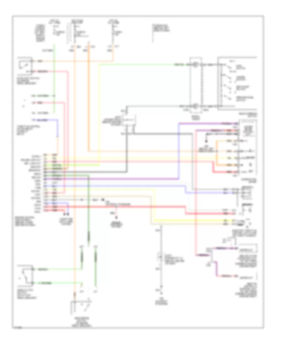
CRUISE CONTROL
Cruise Control Wiring Diagram for Nissan Maxima SE 2003
List of elements for Cruise Control Wiring Diagram for Nissan Maxima SE 2003:
- 11k
- A/t
- A/t m/t
- Abs actuator & electric unit (at left rear corner of engine compartment)
- Abs/tcs control & electric unit (at left rear corner of engine compartment)
- Ascd brake switch (on brake pedal bracket)
- Ascd clutch switch (on clutch pedal bracket)
- Ascd steering switch
- Ascd sw
- Avcc
- Bnc sw
- Brake sw
- Can-h
- Can-l
- Cancel switch
- Close
- Combination meter
- Computer data lines system
- Cruise
- Cruise lamp out
- E83
- Electric throttle control actuator (on throttle body)
- Engine control module (ecm) (behind lower center of dash)
- Engine controls system
- F39 (on front of engine)
- Fuse & fusible link box (at left side of engine compt)
- Fuse 2 15a
- Fuse 30 10a
- Fuse 63 15a
- Fuse block (behind left side of dash)
- Gnd
- Gnd-a
- Hot at all times
- Hot in on or start
- Joint connector 20 (behind center of dash)
- Joint connectot 18 (behind center of dash)
- M/t
- M158
- M17
- M19
- M25 (below left side of dash)
- M32
- M33
- M34
- M644
- Main switch
- Meter out
- Motor 1
- Motor 2
- Motrly
- Nca
- Open
- Red
- Resume/accel switch
- Sensor 1
- Sensor 2
- Set
- Set lamp out
- Set/coast switch
- Spiral cable
- Stoplight switch (on brake pedal bracket)
- Throttle control motor relay (in relay box 2)
- Tps1
- Tps2
- Unified meter control unit
- Vmot
- Vsp-8
- W/ tcs
- W/o tcs
 English