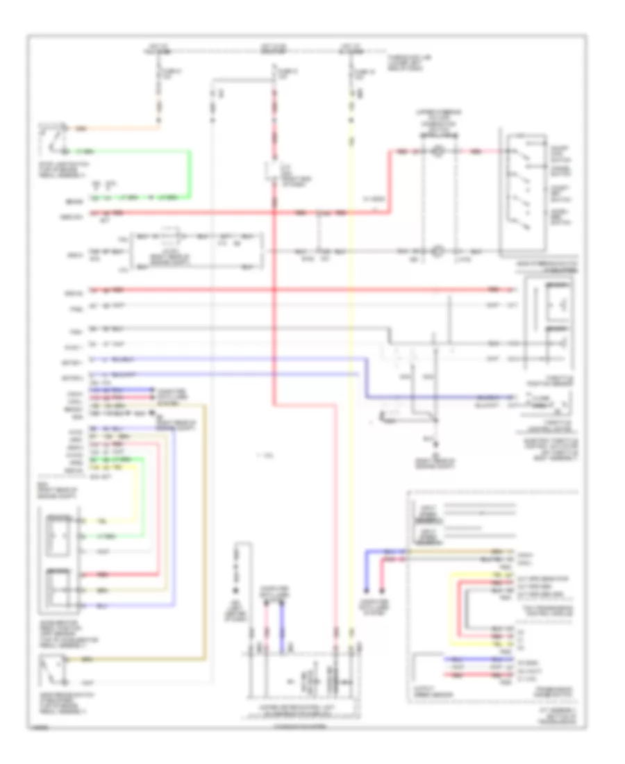
CRUISE CONTROL
Cruise Control Wiring Diagram for Nissan NV1500 S 2014
List of elements for Cruise Control Wiring Diagram for Nissan NV1500 S 2014:
- (upper steering column) combination switch (spiral cable)
- (w/ ascd) cruise ind
- (w/ ascd) set ind
- 13g
- 14g
- 4.0l
- 5.6l
- A/t assembly (bottom of transmission)
- Accel/ res switch
- Accelerator pedal position (app) sensor (top of accelerator pedal assembly)
- Aps1
- Aps2
- Ascd brake switch (if equipped) (top of brake pedal assembly)
- Ascd steering switch (if equipped)
- Ascd sw
- Avcc
- Avcc 1
- Avcc2
- Bncsw
- Brake
- C1 (vin)
- C2 (vout)
- C3 (gnd)
- Can-h
- Can-l
- Cancel switch
- Close
- Coast/ set switch
- Combination meter
- Computer data lines system
- E152
- E16
- E51
- E77
- E9 (right rear of engine compt)
- Ecm (right rear of engine compt)
- Electric throttle control actuator (on throttle body assembly)
- F14
- F502
- F503
- F505
- F506
- F54
- F72
- Fuse 12 10a
- Fuse 19 10a
- Fuse 21 10a
- Fuse block (j/b) (lower left end of dash)
- Gnd
- Gnd-a
- Gnd-a2
- Hot at all times
- Hot in on or start
- Input speed sensor 1
- Input speed sensor 2
- J/c f01 (right rear of engine compt)
- J/c m04 (right end of dash)
- M102
- M23
- M24
- M30
- M31
- M39
- M61 (left center of dash)
- Motor 1
- Motor 2
- Nca
- On/off main switch
- Open
- Out spd sen
- Out spd sen gnd
- Out spd sens pwr
- Output speed sensor
- Pnk
- Red
- Sensor 1
- Sensor 2
- Stop lamp switch (top of brake pedal assembly)
- Tcm (transmission control module)
- Throttle control motor
- Throttle position sensor
- Tps1
- Tps2
- Transmission range switch
- Unified meter control unit (w/ information display)
- W/ ascd
 English